A.5. Analysis
244. In this chapter, the STF set of design rules is introduced by first providing the context and the problem it is addressing. Following, the solution and derived consequences are described. Finally, the limitations, the deviations and examples are presented.
A.5.1. Context
245. As NATO and Nations are evolving to achieve the vision of the NATO Network-Enabled Capability (NNEC), there are four basic challenges which have to be addressed in order to achieve the NNEC requirements that "data, information and services be visible, accessible, understandable and trusted across the networked environment for all authorized users, whether anticipated or unanticipated." Each of these challenges build on top of each other - as one challenge is solved, the next becomes relevant as the new challenge to be addressed.
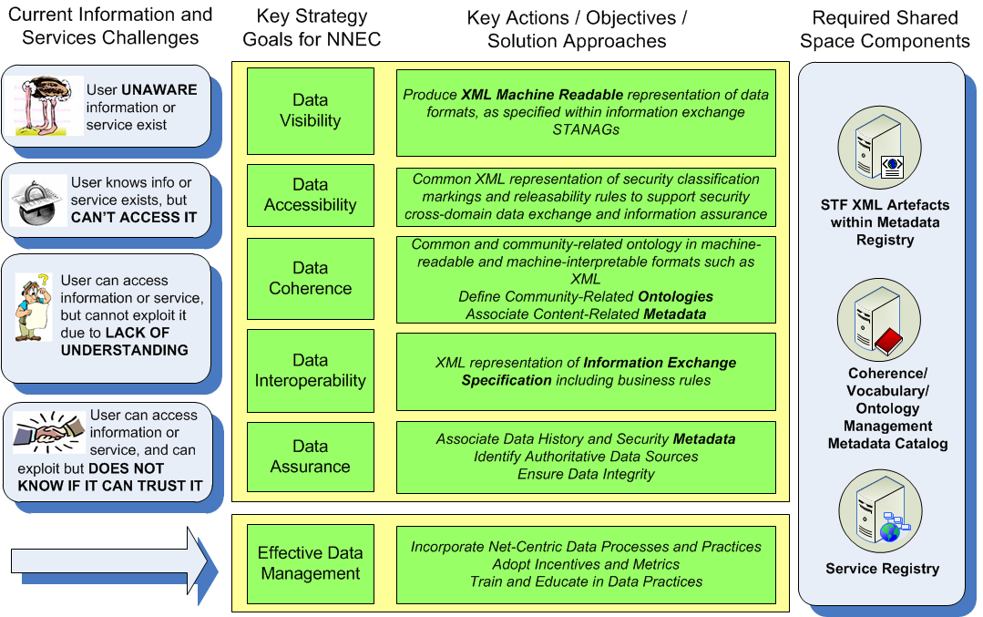
246. As depicted in Figure A.1, these challenges are addressed by six key strategy goals, known as the NNEC Data Strategy goals, of making data Visible, Accessible, Coherent, Interoperable, and Assured, and their related actions/solution approaches. These solution approaches deal with data and information exchanges across a networked environment, and in particular a Service Oriented Architecture (SOA) environment, and thus require standardization of the protocols and data formats to ensure interoperability within the NATO context. As stated in Section A.1.1, these standardisations are captured by NATO as information exchange STANAGs.
A.5.2. Problem areas and opportunities
247. Essentially, NATO has identified several gaps and areas for improvement within the current STANAGs that require action to ensure an appropriate interoperability among forces and to enable the information sharing in a seamless infrastructure.
248. In general, the identified problems are related to the following areas:
-
Lack of ability to efficiently and accurately perform Verification and Validation (V&V) on the quality of the contents and implementations of the STANAGs.
-
Limited resources available for the management and maintenance of the STANAGs.
-
Lack of support to address specific needs to support the NNEC Data Strategy goals.
-
No agreed or standardised approach to the conversion of STANAGS to XML (design rules, methodology).
249. In particular, STANAGs have to be matured in the following aspects, based on the NNEC requirements and their identified gaps:
-
Security matters related both to information exchange security within the same security domain and cross security domains.
-
Operational cross-domain addressing harmonisation of the information being exchanged across-COIs.
-
Open/common architecture framework to describe the enterprise and the common/core services.
-
Service Oriented Architecture enabling seamless sharing of information.
-
Supporting object uniqueness and coherent object identification within a particular COI and among other COIs.
250. The above mentioned areas are further described in the following sections.
A.5.2.1. Lack of automated support for V&V of STANAG content & implementation quality
251. Current STANAGs are text-based documents often composed of many pages (e.g. STANAG 5516 consists of more than 8000 pages). These STANAGs are mainly manually written in text using a natural communication language like English, leaving room for (mis-)interpretations and ambiguous definitions (see e.g. standards ambiguity in [MP-IST-01]). To remove the possibility of misinterpretation and ambiguity, verification and validation of the quality and integrity of the STANAG content is required and needs to be supported in an automated way. The text-based representations of the STANAG do not allow this to happen in an efficient and effective manner.
252. In fact, due to the current status quo, many STANAG standards and implementations may:
-
Contain unnecessary errors, since an automated integrity check cannot occur with a STANAG described in a natural language.
-
Contain inconsistencies when sections of a STANAG are updated as there is no automated means to check and cue updates that are required for other linked sections of the STANAG.
-
Be difficult to browse through without clickable hyperlinks, especially for very large and complex standards.
-
Contain duplications and inconsistencies between the definitions of the same data elements across multiple STANAGs.
-
Have vague or incomplete definitions of important concepts related to information exchanges, such as data bearers.
-
Be subject to restriction from proprietary rights aspects.
253. As STANAGs are currently open to different interpretations, this allows inconsistent implementation of the standards which could lead to interoperability issues when fielded. There is a need for a framework and methodology that supports the transformation of traditional text-based STANAGs into an unambiguous, machine-interpretable format in order to support the automated V&V of STANAG content and implementation quality.
A.5.2.2. Limited resources available for STANAG configuration management (CM)
254. The traditional approach for STANAG definition and maintenance is that a NATO body " in many cases a NATO working group " is responsible for the definition and maintenance of the STANAG based on a well defined process. There currently are limited resources available for the management and maintenance of current STANAGs. In this era where defence budgets are generally in decline with little, if any, prospect for significant improvements, there exists a need to optimize resources to improve the efficiency and effectiveness of the management and maintenance of existing STANAGs and the development of new ones.
255. The current approach for STANAG configuration management and maintenance is a very manual-intensive, stove-piped process that:
-
Results in a tedious and lengthy ratification process.
-
Does not leverage on new technologies and methodologies which would support automatic or semi-automatic verification and validation of the STANAG change proposal content, and assessment of impacts and dependencies before implementation.
-
Is not designed to optimize resources via the re-use of common definitions to support data harmonisation, while increasing quality of the data content.
-
Allows duplications and inconsistencies in the definition of the same data elements between multiple STANAGs as there is no automated way to cross-check the definitions.
256. Once current STANAGs are transformed into a machine-readable and machine-interpretable format, automated tools could be developed to help optimize the limited available resources in order to support the management and maintenance of STANAGs. It will also increase the efficiency in the development of new STANAGs as it supports the discovery, re-use and harmonization of common definitions across the various Communities of Interest (COIs) responsible for STANAG development.
A.5.2.3. Unaddressed shortcomings of current STANAGs
257. The need for making data Visible, Accessible, Understandable and Interoperable in an NNEC (SOA) environment is not fully addressed in current STANAGs.
258. Current STANAGs typically:
-
Have missing definitions of important concepts related to information exchanges, such as data bearers.
-
Do not define how to share information in a Service Oriented Architecture (SOA) environment outside its legacy information exchange stovepipe.
-
Are not sufficiently mature to support information exchange within a SOA.
-
Do not support or address several necessary requirements such as cross COI and cross-security domain information sharing.
-
Do not support object uniqueness and coherent object identification within and between COIs.
259. A structured, layered approach that identifies and captures the gaps and addresses the shortcomings of existing STANAGs in fulfilling the NNEC Data Strategy goals is needed to guide the transformation of existing STANAGs to support information exchange in a SOA environment. It will also assist in future STANAG development to ensure these gaps are addressed at STANAG inception and development rather than costlier and time-consuming changes after the fact.
A.5.3. Solution Introduction
260. In this section, the solution for addressing the identified problem areas and opportunities captured in Section A.5.2, the STANAG Transformation Framework (STF), and its associated layered concepts are introduced. In the following Section A.5.4, the Framework and layers are presented, with an analogy and description per layer that defines the purpose for each layer. Following, in Section A.5.5, the associated design rules, the methodology, a description of the associated XML Schema Definitions and an XML sample are provided for each layer of the STF. These provide guidance to the end users on how the STF design rules and methodology could be applied to transform existing STANAGs or develop new STANAGs in a layered approach and as machine-interpretable STANAG definition.
A.5.3.1. STANAG Transformation Framework (STF) Background
261. As part of the multi-year standards transformation effort, NCI Agency (formerly NC3A) developed, under sponsorship of ACT, the STANAG Transformation Framework (STF) to address the identified problem areas and opportunities captured in Section A.5.2. The STF concepts were first introduced in the RTO sponsored Lecture Series on Interoperability in November 2009 [RTO-IST-088], and has been further enhanced in detail here. The STF is a framework, a set of design rules and a methodology for transforming traditional text-based information exchange STANAGs into an unambiguous, machine-interpretable XML format and providing a layered approach in addressing the needs for maturing the information exchange STANAGs in the areas identified.
262. The standards transformation concept transforms and augments standards by moving towards a more modular composition of the standards differentiating messages structure, data element dictionary, information exchange business rules and other aspects. To fulfil the emerging NNEC requirements, the current standards will be augmented with additional specifications, such as security cross-domain information exchange definitions.
263. Moreover, the transformation of current standards towards machine-interpretable standards is foreseen as part of the standards transformation concept. The expanding exploration and application of XML into the realm of information exchange is viewed as a major step in support of NNEC. An evolving framework for capturing information exchange specifications in XML is a key element in advancing this technology. As that framework matures it is imperative that it adopts a model which fully supports all types of information exchanges, i.e. binary-, text- and XML-based formats. This will improve quality, maintainability and integrity of the standards and therefore contribute to the NNEC Networking and Information Infrastructure (NII) by improving interoperability.
264. A common framework and methodology applicable to all STANAGs, which are related to the technical interoperability between systems/services, was developed. The combination of the two will allow the NNEC Data Strategy goals to be addressed and they will facilitate the implementation of it from a standardization perspective.
A.5.3.2. Concepts
265. Below a number of concepts specific to the STF set of design rules are described.
-
Layered approach: The purpose of each layer is to offer services to its neighboring layers, avoiding those layers from being affected from changes in the internal details of their neighboring layers, and from how the offered services are implemented. The linkages between different layers, is regulated by specific interfaces. The principles used in internetworking can be taken as analogy. As a consequence, layers can also be re-used or interchanged.
-
Interface:The place where two different systems interact, normally in accordance with an agreed contract.
-
Human Readable:A human-readable medium or human-readable format is a representation of data or information that can be naturally read by humans. In computing, human-readable data is often encoded as ASCII or Unicode text, rather than presented in a binary representation. This can also refer to the shorter names or strings that are easier to comprehend or remember rather than the longer, more complex syntax notations, such as some URL strings.
-
Machine Readable: A machine-readable format or medium of data primarily designed for reading by electronic, mechanical or optical devices, or computers. For example, the binary representation of data used by computers, the UPC barcodes for scanners, or the URL strings.
-
Machine Interpretable: More than just being readable by machines, machine interpretable data or format contains structured content that can be processed and "understood" by machines.
-
Bit-based: the information is encoded in a binary representation to optimise bandwidth usage, e.g. Link16 or VMF. This representation is generally not easily human readable.
-
Structured Text-based: the information is represented as textual values and the structure of the message is governed by other means e.g. line-based and slash delimited like for MTF and OTH-Gold. This representation is typically human and machine readable, but may not be easily machine interpretable.
-
XML-based: the information is represented as textual values and the structure is governed by an XML Schema Definition (XSD) in line with the [W3C-XML], e.g. MTF-XML or NFFI. This representation is highly machine-readable and machine-interpretable.
A.5.4. STF Layers and Definition
266. Leveraging the successful application of the layered approach similarly to that of the ISO OSI reference model, the STF is defined using a layered approach to identify and capture the different areas of the information exchange STANAGs that should be specified in order to support various levels of interoperability. The STF layers have been identified based on the analysis of current Information Exchange Requirements and Specifications and emerging requirements for information sharing. The STF defines clear interfaces between the layers, supported by machine-interpretable XML specifications, design rules and a methodology to apply them, in order to support the identification, capture and reuse of specifications within those layers to support information exchange interoperability.
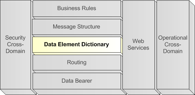
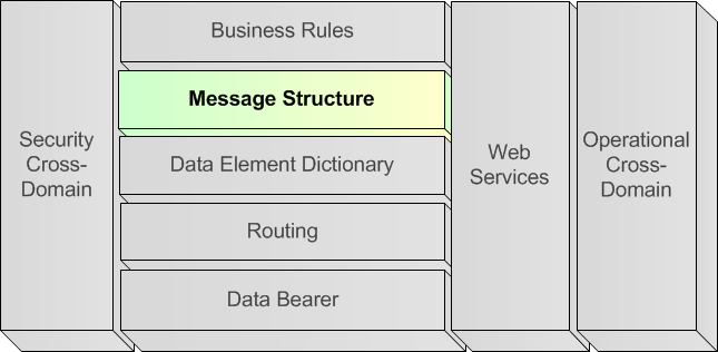
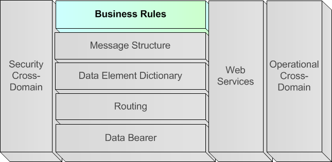
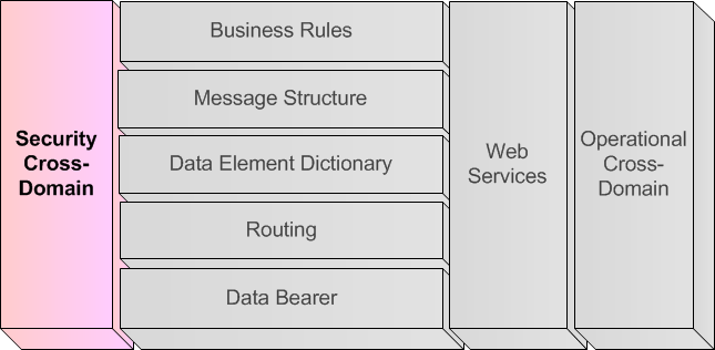
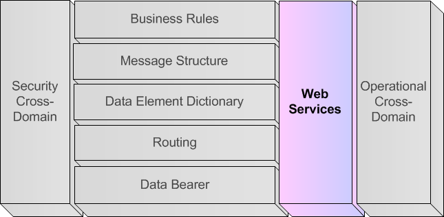
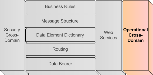
267. The logical view depicted in Figure A.2 provides an overview of the identified STF layers necessary to ensure appropriate data and information dissemination.
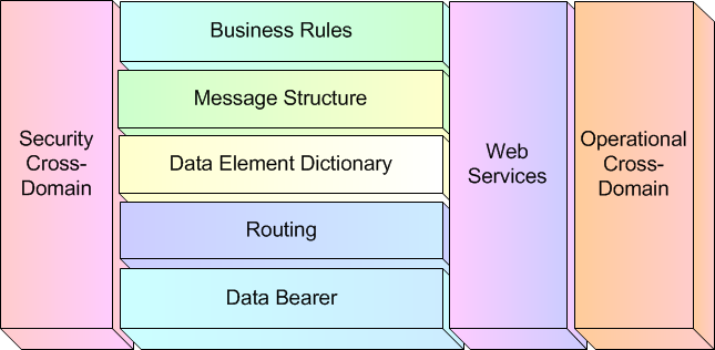
268. As can be seen, the STF defines five stacked horizontal layers and three vertical layers.
269. The application of the STF layers towards STANAG transformation is based on the intended use and need to support interoperable information exchange within different domains.
270. The horizontal STF layers could be considered Mandatory; their specifications are needed to support interoperable information exchange within a domain. However, a particular system implementation might not need to provide all functionalities described within the STANAG--the functionalities might be implemented by various systems, each playing a different role within the functional scenario. Therefore, the deployment or implementation of a system might cover only a subset of the layers to cover their needs and roles. This way the minimum implementation requirements for each system to achieve interoperability within a functional scenario must specify the requirement to implement parts of each layers to fulfil a specific role in a functional scenario.
271. On the other hand, the vertical layers could be considered Optional specifications based on the intended use and functional scenario. In particular, if it is determined that there is a need to support the exchange of information across different security domains, then the specifications to support that information exchange has to be captured at the Security Cross-Domain layer. If it is envisioned that there is a need to support the exchange of information utilizing web services, then the Web Services specifications have to be captured using the Web Services layer. And finally, if it is deemed necessary to support the exchange of information across operational domains, it is necessary to map and specify how that information exchange will occur between those domains using the Operational Cross-Domain layer.
272. The horizontal layers leverage concepts that can be loosely mapped to the ISO OSI 7-layer model, TCP/IP stack and communication protocol specifications.
273. The first two horizontal layers, "Data bearer" and "Routing", deal with physically and logistically "how" the information exchange is occuring between two systems. These two layers can be mapped to the lower 5 layers of the OSI model or the lower 2 levels of the TCP/IP stack, namely the Physical and Data Link layers, and the Network, Transport and Session layers. These deal with getting the data between any two or more systems that need to interoperate with each other.
274. The top three horizontal layers defines "what" is being exchanged and the "rules" for exchanging those messages between two or more systems. These layers map loosely to the data defintion, data syntax, data semantics and data synchronization concepts used to define communication protocols at the Application layer of the OSI and TCP/IP stack.
-
The "Data Element Dictionary" and "Message Structure" define the data representation and syntax of the information exchange which define the context of the information exchange.
-
The "TX + RX rules/busines rules", focuses on the semantics and synchronization of the data exchange, which defines how to send, receive and interpret the messages so that they make "sense", defining the rules that determine whether the data is meaningful.
275. The STF has been defined in such a way that the layers are generic and applicable to all types of information exchanges. The machine-interpretable XML specifications provide, where required, support for the different types of exchanges by defining a specific adapter of the XML Schema Definition (XSD). In the case of XML-based information exchanges the STF will leverage on the existance of a compliant XSD governing the information exchanges augmented with further required information.
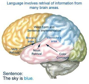
276. The following sections will describe each of these layers starting with an analogy to compare the relevant aspects of automated information exchange with a scenario everyone will be familiar with: natural language communication.
A.5.4.1. Data Bearer
A.5.4.1.1. Analogy
277. The information exchange via a language can be achieved in different ways. The usage of the verbal communication is probably the preferred communication media, either directly in a local discussion or via a transport medium like a phone. Nevertheless, language can also be used to exchange information via textual media (either electronic or paper-based), television and chat.

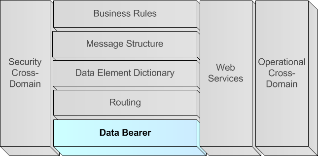
A.5.4.1.2. Definition of Data Bearer layer
278. The data bearer information is composed of the information in the lower 2 layers of the ISO OSI models, which are the physical and data link layers of the OSI network architecture.
-
Physical Layer defines the electrical and physical specifications for devices. In particular, it defines the relationship between a device and a physical medium.
-
Data Link Layer provides the functional and procedural means to transfer data between network entities and to detect and possibly correct errors that may occur in the Physical Layer.
279. The description within a STANAG of the possible data bearers used within the interfaces is essential to achieve interoperability between system and services.
280. In case multiple data bearers can be used for information exchange, all of them have to be described here, including a rationale why the information exchange node should choose one or the other data bearer in specific situations.
A.5.4.2. Routing (Horizontal Layer)
A.5.4.2.1. Analogy
281. The distribution of information via language is addressed to a specific audience and thus does not occur unconditionally and to everyone. A conversation occurs only in between the participants of the conversation. The chat can be addressed one-on-one or to multiple chat participants, whereas the distribution of the newspaper occurs on a subscription basis.

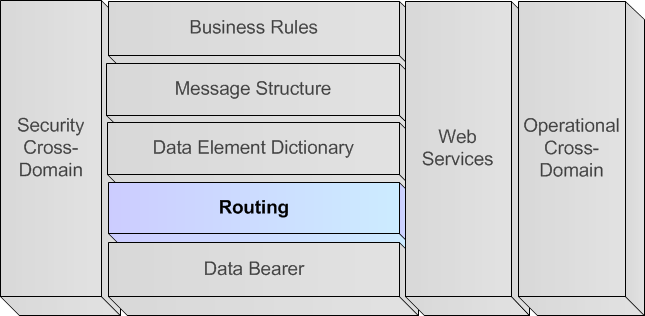
A.5.4.2.2. Definition of Routing layer
282. The Routing layer overlaps with the 3rd, 4th and 5th layers of the OSI reference model for network communication, which is typically referred to as the Network, Transport & Session layers.
-
Network Layer provides the functional and procedural means of transferring variable length data sequences from a source to a destination via one or more networks, while maintaining the quality of service requested by the Transport Layer. The Network Layer performs network routing functions, and might also perform fragmentation and reassembly, and report delivery errors.
-
Transport Layer provides transparent transfer of data between end users, providing reliable data transfer services to the upper layers. This Layer controls the reliability of a given link through flow control, segmentation/desegmentation, and error control. This Layer can be thought of as a transport mechanism, e.g., a vehicle with the responsibility to make sure that its contents (passengers/goods) reach their destination.
-
Session Layer controls the dialogues (connections) between computers. It establishes, manages and terminates the connections between the local and remote application. It provides for full-duplex, half-duplex, or simplex operation, and establishes checkpointing, adjournment, termination, and restart procedures.
283. The routing of the information dissemination between two or more parties needs to be explicitly captured within STANAGs.
284. Current technology defines the routing of information in heterogeneous ways, which tend not to be interoperable. A lack in specifying the routing mechanism will lead to interoperability issues. In case multiple routing algorithms can be used for information exchange, all of them have to be described within the STANAG, including a rationale why the information exchange node should choose one or the other routing mechanism in specific situations.
A.5.4.3. Data Element Dictionary (Horizontal Layer)
A.5.4.3.1. Analogy
285. The definitions of words within a language are captured in a dictionary, where each word can have one or multiple meanings in that language. Sometimes the meaning is explicitly stated in the dictionary, in other cases, the meaning of the word is associated with non-verbal communication or tonality of pronunciation. The meaning expressed by a word within a certain language, can be expressed by multiple words within the same language and in other languages.

A.5.4.3.2. Definition of Data Element Dictionary layer
286. Within an information exchange STANAG, a data element is the atomic unit of data that has a precise meaning and precise semantics for that domain. Such a data element can be stored or exchanged among computer systems. The catalogue containing all Data Elements within a certain domain is called a Data Element Dictionary (DED) for that domain.
287. It has to be stressed that proper and clear data element definitions are critical for external users of any data system, since a good definition can ease the process of data element harmonisation, where one set of data elements are mapped into another set of data elements.
A.5.4.4. Message Structure (Horizontal Layer)
A.5.4.4.1. Analogy
288. Providing words in a non-structured way will pass only very limited information. Every communication language defines the grammar to construct sentences and therefore disseminate the information in an understandable way, to whoever knows the words and the language grammar. The human is capable of interpreting, assuming and correcting grammar mistakes, and thus understanding the information even if not completely properly structured.

A.5.4.4.2. Definition of Message Structure layer
289. To ensure interoperability between systems, it is essential that the data exchange is conforming to specific syntax rules. This syntax is called the message structure, which defines:
-
A packaging of one or multiple levels of data elements into logical and/or functional groups, and;
-
The sequencing of data elements within each functional and/or logical group.
290. A proper structure will enable the association of data elements with each other, in order to support the binding of data to certain functional or logical objects. For example, the exchange of an altitude without context expresses less information than the exchange of an altitude related to a certain object. By using multiple level packaging, information about multiple objects, or even sub-objects, might be exchanged within one message.
A.5.4.5. Business Rules (Horizontal Layer)
A.5.4.5.1. Analogy
291. "The Grammar of Ornament", a "new geographical and historical grammar" (London, 1764) and "Augustus as Ruler of Rome" summarize the explicit and implicit aspects of a dialogue. Knowing the available words and the valid sentences (see grammar of the language) that can be formed using these words, does not imply the capability to participate in dialogue. A dialogue follows explicit and implicit rules; if a question is asked, a related answer is expected, if a statement is made, a related statement or follow-up is expected.

A.5.4.5.2. Definition of Business Rules layer
292. While the Message Structure and Data Element Definition (DED) provide the more static description of the way messages are constructed and how data elements are coded, the business rules / transmission reception rules aspect of the standard is defined as what behaviour a system should follow when handling the messages, the interaction with an operator or with the underlying system (e.g. its sensors' output). The business rules / transmission reception rules describe the dynamics of an automated message handling system.
A.5.4.6. Security Cross-Domain (Vertical Layer)
A.5.4.6.1. Analogy
293. The human tailors the type of information he provides to the audience and to the context, withholding information that is not releasable to (a part of) that audience or in that specific context.
294. In a conversation a party can put explicit constraints on the further distribution of provided information. The judgement, whether or not to share information is based on specific rules (e.g. need-to-know principle, personal in confidence attributes) but also on perception.

A.5.4.6.2. Definition of Security Cross-Domain layer
295. The Security Cross Domain takes into account recommendations provided in Bi-SC Secure C2 Data Strategy with security requirements aspects being subdivided into two categories:
-
Requirements for information exchange within the classification at the same level (important if connected to unsecure networks like the Internet), and
-
Requirements for the security cross-domain functionalities.
296. The latter can be omitted in case only a single security domain is involved.
297. For security requirements within a homogeneous security domain, the security aspects might contain:
-
Information on security related protocols / services (HTTPS).
-
Information on data source authentication and authorisation.
298. For cross-domain security, the aspects might contain;
-
Appropriate security labelling (in-line with NATO standards [NAC-INFOSEC] and recommendations [RTO-XML-2008] [RTO-XML-2009]) including the specification of what information should be considered classified (at what level) and what information should be considered unclassified
-
Possible rules for sanitization of data, defining the manner to downscale the classification of information, e.g. information might be classified during a certain operation or exercise, but unclassified after the operation finished. Sanitization rules should be used to define this.
-
Information integrity: If information is labelled with the purpose to exchange it cross-security domain, the boundary device should be able to verify that the information has been labelled by a trusted device, and that nobody tampered with the label or the data in between the labeller and the boundary device (e.g. Public Key Identifier (PKI).
A.5.4.7. Web Services (Vertical Layer)
A.5.4.7.1. Analogy
299. The presence and the wellness of a person, imply that the person is in the position to provide the information in his hands. In addition to being aware of the presence of a person, one should also recognize the person (knowing the person) and know for example his profession or the type of information he can provide, in order to collect useful information from that person. Moreover, a person can attend a meeting for multiple purposes: learn (listening only), actively contribute (active dialogue) or provide information (giving a presentation).
A.5.4.7.2. Definition of Web Services layer
300. The web services specification chapter will mainly be used when the information exchange can take place via web-services. The web-services description will contain at least the following components:
-
Information exchange scenarios for the Service Oriented Architecture information exchange (containing information on whether data will be pulled or pushed, using mechanisms like publish-subscribe, request-response, etc.).
-
A detailed description of the web-services interface, defining the methods that can be called, arguments to be provided and answers to be expected. This part might refer to schemas and WSDL file.
-
The Service Metadata specification, which will contain the description of the services based on a set of metadata containing useful information for all COIs, to enable the discovery of the information providers.
A.5.4.8. Operational Cross-Domain (Vertical Layer)
A.5.4.8.1. Analogy
301. Within the usage of a common language such as English, different users will develop their own vocabulary and associated specific meaning to words related to their core business. If a patient with a basic knowledge meets a doctor and the doctor does not adapt his vocabulary (medical terminology) to the daily vocabulary, the patient will not really understand what the doctor says. Sometimes the patient might have the perception to understand the doctor since he has a vague idea of the meaning of medical terms, but for sure he will not grasp the details. Moreover, a person visiting a foreign country needs a translator to help him communicate with the local people in case he does not speak the local language. Unfortunately, in most of the translations, a loss of information and meaning will occur.
A.5.4.8.2. Definition of Operational Cross-Domain layer
302. Many information exchange STANAGs are normally developed with usage limited to one specific Community of Interest (COI), leading to the development of ad-hoc vocabularies to fulfil their immediate requirements. The data elements definitions are specifically oriented to the COI with direct impact on quality within the COI specific network and interoperability with other COI specific systems, with little to no consideration of existing STANAGs within or between other COIs.
303. This typically results in a lack of interoperability both within the COI (because of the availability of multiple COI specific standards) and between COIs.
304. The Operational Cross-Domain layer is provided to capture those information exchange specifications between COIs or STANAGs at the necessary levels as identified in the horizontal layers.
305. For example, the data elements defined within two COIs' information exchange specifications could be fully overlapping, disjointed or partially overlapping. It is essential to associate these data elements and their relationships based on the context and content of the information exchange in order to achieve interoperability between the COIs. The mapping and harmonization of semantically the same data elements and the association of similar data elements has to be captured.
A.5.5. STF Design Rules & Methodology
306. In this section, for each layer of the STF, the design rules are provided together with a description of the supporting XML Schema Definition with examples, followed by the methodology of applying the design rules and utilising the XML Schema Definition.
307. For STF Version 1.0, the STF Design Rules & Methodology section is scoped to the following:
-
Data Element Dictionary (DED):
-
Bit-based
-
Structured text-based
-
-
Message Structure (MS):
-
Bit-based, Fixed-length
-
308. For plans for the STF Design Rules, please consult section Section A.12.
A.5.5.1. STF Holistic Process
309. The definition, application and V&V of the STF layers, design rules and methodology is an on-going process that is handled by the iterative process captured in Figure A.10. This is a Holistic Process that can be applied to the STF itself as well as for the application of the STF in transforming textual IESs into XML. There are explicit points identified for feedback to the STF and IER/IES Stakeholders for possible improvements of their products.
310. For STF Version 1.0, the STF Holistic Process is depicted below. It is anticipated that this Process will be expanded for future versions as additional STF layers are matured and provided. For example, once the Business Rules layer has been expanded upon, an additional step will have to be added to cover that layer.
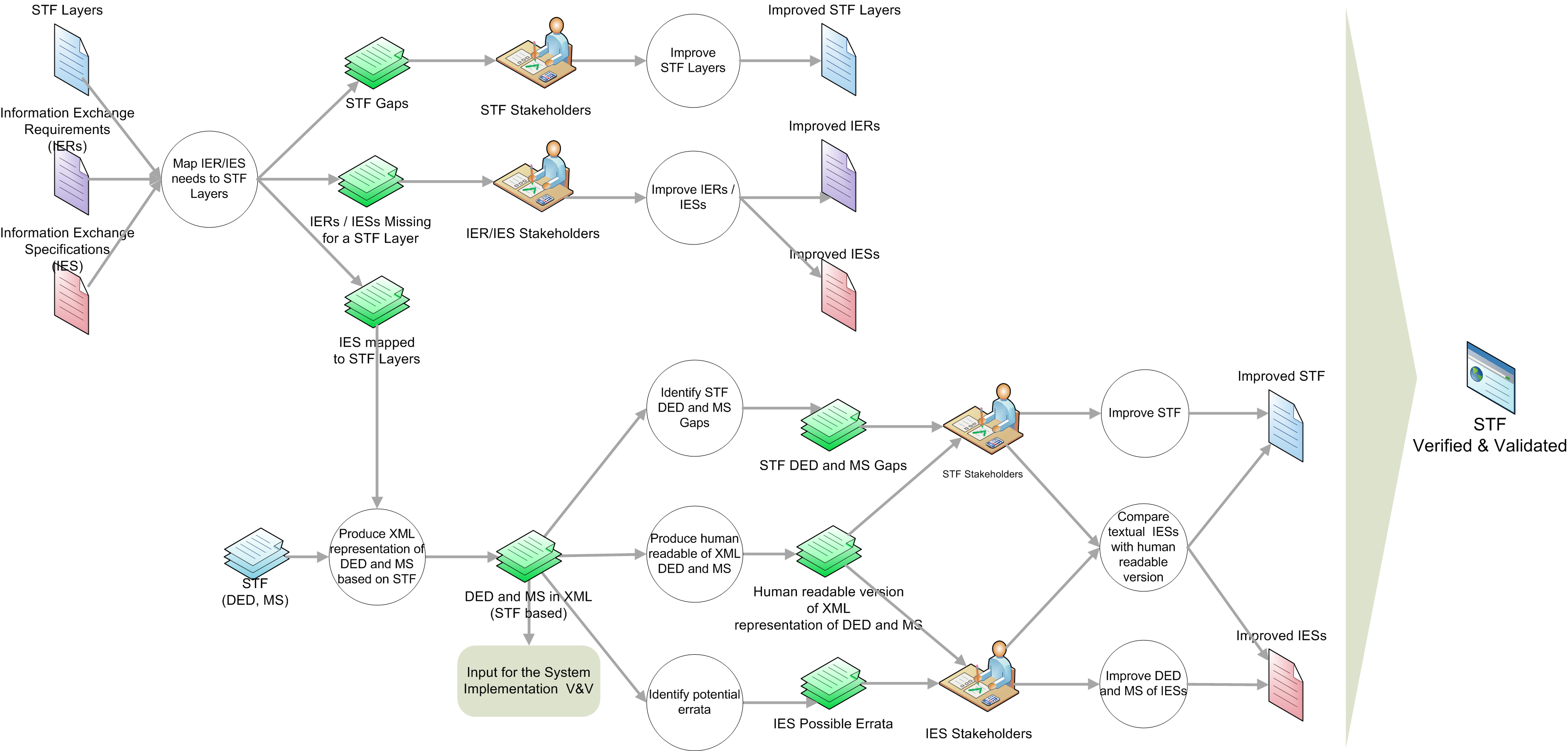
311. The STF Holistic Process is detailed in the rigorous steps below:
-
Map IER/IES needs to STF Layers. Analyze the IERs with regards to the STF layers to identify the need for specifications at those layers (i.e. if there is a requirement to exchange the Information Product via Web Services, then a specification for the Web Services STF layer would be necessary). Based on these needs, identify existing Standards (IESs) that could fulfill those needs. With the STF layered approach, one may find that the same IESs can be reused to fulfil multiple types of IERs as well as find that there will be missing IESs that need to be developed to fill gaps in the STF layers for that IER. The findings can be analysed and corrective actions can be taken by the appropriate stakeholders. In particular, possible outcomes of this step could include the following:
-
Identified STF gaps where no STF Layer captures IER/IES needs, which should be captured and forwarded to the STF Stakeholders for the possible opportunity to Improve the STF.
-
Identified IES gaps where no Standards could be found for a particular layer, which should be captured for submission to the appropriate IER/IES Stakeholders for analysis. Results could be the possible opportunity to Improve current Standards with the adoption of existing IESs to close the gap or lead to the development of new IESs.
-
Identified IESs to fulfil each identified STF Layer needed to fulfil IER. For the IESs that specify the format and message structures of the information exchange,
-
Produce XML representation of DED and MS based on STF. Apply the STF XML schemas at the DED and MS Layers to capture the valid data elements that can be exchanged as part of the information exchange, the order in which they can occur, and constraints on certain aspects of these message exchanges in XML representations. Outcomes of this step could include the following:
-
Identified problems/gaps within the STF XML schemas for sufficiently capturing the information exchange DED and MS, which should be captured and forwarded to the STF Stakeholders for the possible opportunity to Improve the STF.
-
Identified problems within the textual IESs, which should be captured as Possible Errata for submission to the appropriate IER/IES Stakeholders for the possible opportunity to Improve the Standards.
-
XML files of transformed Standards. Once the Standards have been transformed into XML, the XML files have to be V&V'd to ensure they properly capture the existing IES. Using existing XML Technology and Tools, one is able to perform the following V&V steps on the resultant XML files:
-
Automatic Conversion to Human-Readable Formats. Automatically produce the equivalent human-readable documents from the XML files to be provided to the IES Stakeholders to be analyzed for correctness. Results of this could be exploited to Improve the Standards.
-
-
-
-
A.5.5.2. Data Bearer Design Rules & Methodology
312. Not yet addressed within the current version of the STF.
A.5.5.3. Routing Design Rules & Methodology
313. Not yet addressed within the current version of the STF.
A.5.5.4. Data Element Dictionary Layer Design Rules & Methodology
314. The purpose of the Data Element Dictionary layer is to capture the data elements, or vocabulary, of the Information Exchange STANAG.
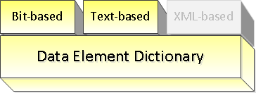
315. In general, there are different types of Information Exchanges that can occur which can be categorized based on the way the data being exchanged between systems is represented. In particular, within the STF, the following three types have been identified-- bit-based, text based and XML-based, the last being a highly-structured text based information exchange.
316. The STF Data Element Dictionary layer has been defined in such a way that it is applicable to all types of information exchanges. The machine-interpretable STF-related XML specifications provide, where required, support for the different types of exchanges by defining a specific adapter of the XML Schema Definition.
A.5.5.4.1. DED Concepts
317. ISO/IEC 11179 Data Modelling
318. As considered by ISO/IEC 11179, there are three main relationships related to semantic theory and the basic principles of data modelling that should be addressed when identifying, defining and grouping data elements. These are the following:
-
Between generic and more specific concepts (e.g. "Altitude" vs. "Altitude in 25 FT increments above MSL")
-
Between a concept and its terminology (e.g. "Location" vs "Position")
-
Between a concept and its usage/context (e.g. "Latitude" + "target" = "Latitude of target")
319. Within STF, the first two relationships are captured within the Data Element Dictionary layer. The third relationship can be captured either in the Data Element Dictionary or in the Message Structure layer (see below).
320. Usage vs. Context
321. In Merriam-Webster online dictionary, the word context can refer to two slightly different, but related meanings:
-
the parts of a discourse that surround a word or passage and can throw light on its meaning
-
the interrelated conditions in which something exists or occurs : environment, setting
322. Within STF, the context, or the third data modelling relationship, can be captured either explicitly as a different Data Element or implicitly as a data field within the Message Structure layer. The reason for this is that, often, the specific meaning of a Data Element could be provided by how it is being used (i.e. Latitude of target vs Latitude of shooter). However, the context could also describe the environment in which the data element exists (i.e. Latitude is a data field within the Target Position Message). This could be considered a different usage, hence a different Data Element, but not necessarily so.
323. Furthermore, the type of Information Exchange may have impact on the way the Data Element Concept and Data Elements are defined as e.g. the different representations of bit-based Information Exchanges might be considered different uses.
324. For the purpose of the STF and to support reuse and data harmonization, it is highly recommended that the end user captures the context relationship within the Message Structure layer rather than as an explicit data element.
325. Data Element Concept/Data Elements
326. These are two related concepts within the STF Data Element Dictionary layer that capture the first two relationships. The Data Element Concept maps to the generic, "conceptual" concept while the Data Elements map to the more specific, "concrete" concepts. In particular, the Data Elements in the STF DED are organised based on a thesauri, in support of the Data Coherence goal of the NNEC Data Strategy, whereby the Data Element Concepts group together semantically equivalent data elements that might be represented within a STANAG using different terminology and/or granularity. Different possible instantiations of a Data Element Concept are described with the use of one or more Data Elements.
327. Data Element
328. A Data Element captures a specific concept with a specific representation, and possibly with a specific usage. It is the atomic unit of data that has a precise meaning and precise semantics for that domain. Such a data element can be stored or exchanged between computer systems.
329. Some important Data Element properties:
-
Data Elements are instantiated in the context of a message as a Data Field (see further 5.5.4) in the Message Structure layer.
-
As defined, Data Elements are atomic units of data, and therefore are unstructured (e.g. non-complex types). To capture parent-child relationships, data elements should be instantiated as data fields within a Word of a Message Structure.
-
Data Elements provide the information on how to handle and interpret the value as exchanged, i.e. how to decode the value as transmitted to something meaningful for computers or humans and how to encode such meaningful value to the representation for transmission. This is similar to the "serialization" concept in information systems.
-
For example, the exchange representation might be some binary or string value, for which the meaningful value might be the altitude in meters or the country name.
-
-
The coding information of a Data Element can specify a mapping between exchanged values and the real values, e.g. mapping the text value NL to The Netherlands for a text-based Information Exchange or mapping the numerical value 3 to FRIEND for a binary Information Exchange.
-
For numerical Data Elements, the specification can include a conversion method from the exchanged representation to the meaningful value, e.g. a binary value might indicate the altitude in multiples of 10 meters.
-
Additional information is captured on the meaning of the Data Element, e.g. in the case of numerical values which unit the value has (degrees, data miles, meters, etc) and which type (integer or floating point number, boolean, etc).
-
In the situation where the coding of a Data Element depends on the value of another Data Element, the DED provides a construct called a CodingSwitch | Coding Switch. The Coding Switch construct allows to capture explicitly which other Data Element (actually, the instantiated Data Field version) should be inspected and depending on its value how the first Data Element should be decoded/encoded. For example, a Scale Indicator Data Element might control that the Altitude Data Element is reporting the altitude in multiples of 100 or 500 feet increments. This construct is especially used in the binary information exchanges for space optimization.
330. Within the STF, a data element is composed of and defined by:
-
An identification including the data element name and a unique identifier:
-
The name given to the data element within the context of the STANAG, not necessarily unique although recommended.
-
The unique identifier is used to uniquely refer to the Data Element within the context of the STANAG.
-
-
A clear data element definition:
-
A human readable phrase or sentence associated with the data element within a data dictionary that describes the meaning or semantics of a data element.
-
-
One or more representation terms:
-
A word, or a combination of words, that semantically represent the data type (value domain) of a data element.
-
-
Optional enumerated values:
-
System of valid symbols that substitute for longer values ISO/IEC 11179.
-
-
An optional list of synonyms to data elements in other STANAGs or Metadata Registries:
-
Data elements that are considered semantically equivalent for the purposes of information retrieval.
-
-
Optionally, additional metadata depending on the type of information exchange.
331. It has to be stressed that proper and clear data element definitions are critical for external users of any data system, since a good definition can ease the process of data element harmonisation, where one set of data elements are mapped into another set of data elements.
332. Data Element Concept
333. The Data Element Concept is the agreed upon term for a generic concept used to represet a set of common data elements.
334. Within the STF, a data element concept is identified by:
-
The Name given to the Data Element Concept within the context of the STANAG, not necessarily unique although recommended
-
The Data Element Concept Identifier, which is the unique identifier used to refer to the Data Element Concept within the context of the STANAG.
335. Data Element Dictionary
336. A collection of data element concepts and associated data elements that are used to specify the message exchange. Within STF, the XML file containing all Data Elements within a certain domain is called a Data Element Dictionary (DED) for that domain.
337. Data Element Concept/Data Element Identification (DECI/DEI)
338. To promote reuse, to ease harmonization and to provide meaning to the data elements, it is necessary to be able to uniquely identify each Data Element in an explict and unambigious way. Each Data Element Concept is identified by a numerical ID, data element concept identifier (deci), unique within the particular dictionary and each Data Element is identified by a numerical ID, data element identifier (dei), unique within a Data Element Concept.
339. The combination of the DECI/DEI values is used to uniquely reference a particular Data Element. This approach can be easily mapped on that used by various other communities to reference Data Elements, for example:
-
the MTF community uses the FFIRN/FUD (Field Format Index Reference Number/Field Use Designator)
-
the TDL community uses the DFI/DUI (Data Field Identifier/Data Use Identifier)
340. Data Element Concept/Data Element Examples
341. The following table provides some examples of Data Element Concepts and Data Elements.
| Data Element Concept | Data Elements |
|---|---|
| Altitude | Altitude in 25 FT increments, Altitude in 100 FT increments |
| Heading | Wind direction, Course |
| Latitude | Latitude (accurate in 0.04 minutes), Latitude (accurate in 0.005 minutes) |
| Platform | Air platform, Surface platform, Subsurface platform, Land platform, Space platform |
A.5.5.4.2. Data Element Dictionary Logical Model
342. This logical model shows the relationship between these concepts to support the definition of a generic data element dictionary to be used for information exchanges. The attributes shown in the classes denote relevant information that needs to be captured on the classes or indicate a relationship between classes (e.g. dei).
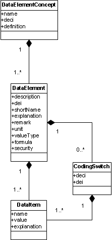
343. The Data Element Dictionary XML Schemas are derived from this logical model, fully elaborated to include all components (elements and attributes) that are required to model the generic data element dictionaries for all types of information exchanges.
A.5.5.4.3. Known Limitations
344. There are some known shortcomings in Version 1.0 of the STF Data Element Dictionary XML Schemas and Logical Model in supporting all types of information exchanges. These are described here:
-
The logic behind a Formula is not represented in machine-interpretable XML and is therefore still open for interpretation by developers etc. Alternatives are defining standard Formulas (stored in a catalogue) which can be referenced from the data elements. The standard Formula can use XML elements to describe e.g. simple mathematical operations (e.g. multiplication with a certain factor). More complex operations (e.g. for positional information like latitude and longitude) will require more work or maybe even external references.
-
The Unit of a DataElement is defined as a simple string (e.g. "METER", "SECOND", "DATAMILE") without any restriction or coupling to external standards. Whenever there is a standard defining such unit there should be a way to link to that.
345. These are being considered although not yet planned for the next version of the STF Design Rules.
A.5.5.4.4. DED Design Rules
346. Based on the type of information exchange and data representation of the Data Elements, a specific adapter (extension) of the common Data Element Dictionary XML Schema (DataElementDictionary-*.xsd) shall be used to capture the Data Elements in an XML representation to fulfil the Data Element Dictionary layer of the STF.
347. Below are the design rules with the methodology on how to apply them to create the STANAG-specific XML file that captures the data element dictionary for a particular information exchange:
348. Rule 1: The DataElementDictionary-BitBased.xsd shall be applied in case the Information Exchange is bit-based, e.g. GMTI, Link16, DIS.
349. Rule 2: The DataElementDictionary-TextBased.xsd shall be applied in case the Information Exchange is based on structured text, e.g. MTF.
350. Rule 3: (Future work) - The DataElementDictionary-XMLBased.xsd shall be applied in case the Information Exchange is based on XML. This XSD is not provided within the current version of the STF.
A.5.5.4.5. Methodology for Data Element Dictionary definition
351. Step 0: Based on the process in place for defining the IES, like [APP-15], decide on the required type of message exchange being bit-based, text-based or XML-based.
352. Step 1: Data Elements Guidance|Identify all Data Elements, being the atomic units of data required for the information exchange.
353. As you are identifying your Data Elements, start to group similar data elements together that share the same functional concept, but have different representation or view. For instance 'Latitude Degrees Minutes Seconds' and 'Latitude Decimal Degrees' both share the same concept 'Latitude', but are expressed by using different data representation types.
354. Step 2: For each Data Element, define the following:
-
Identification:
-
Typically the name of the data element as defined in the STANAG, e.g. "latitude" from NFFI or "Country Code" from APP-6A. If the STANAG defines similar data element concepts with the same formats, but use different "labels" or "names" for them, such as "Identification" vs. "ID", they should be defined using the same data element.
-
Assign a Data Element Concept Identifier (number) and a Data Element Identifier (number), consulting the custodian for guidance.
-
-
Data element definition:
-
Text that describes the meaning or semantics from the data element, e.g. "Angular distance north or south of the earth's equator measured in decimal degrees WGS-84" or "Identifies the country with which a symbol is associated"
-
-
Representation terms:
-
Semantically represents the data element covering the data type and, if applicable, the unit, e.g. for a latitude specify double as type and decimal degrees as unit, or specify for Country Code string as a type and no specified unit.
-
-
Enumerated values:
-
The list of mappings between symbols and their meaning, if applicable.
-
-
Synonyms:
-
Identify data elements within other STANAGs or meta data registries that are interchangeable in the context without changing the truth value of the proposition in which they are embedded
-
355. Step 3: If defining a new Data Element, verify whether an existing Data Element can be re-used by consulting the preferred data element within the meta-data registry (see Data Elements Guidance| Data Harmonization).
356. Step 4: Depending on the type of information exchange, additionally define the following:
-
For bit-based information exchange:
-
Specify the length in bits of the Data Element for exchange
-
For numerical data elements, specify the used bit-coding which captures how a value is represented in binary, in particular relevant for signed numbers (e.g. unsigned, twos-complement, ...).
-
-
For text-based information exchange:
-
Specify the character set allowed for exchange, e.g. only "alphanumeric and dash" and/or a regular expression specifying what values are allowed
-
Specify the minimum and/or maximum length in characters, e.g. 10-30
-
-
For XML-based information exchange:
-
It is supposed that an XSD is defined within the STANAG that defines the XML data elements. If this is not the case, first define this XSD.
-
With respect to the data element dictionary, map every Data Element Concept to the corresponding XML element in the XSD.
-
More specific steps will be provided in STF version 2.
-
357. Step 5: Once the data elements have been defined create the XML document representing the DED for the STANAG. For that, apply the respective XML Schema as prescribed by the design rules to populate with the information identified above.
A.5.5.4.6. Description of the DED XML Schema Definitions
358. The following sections describe the XML Schema definitions used to capture the Data Element Dictionary.
A.5.5.4.7. Base DataElementDictionary XML Schema
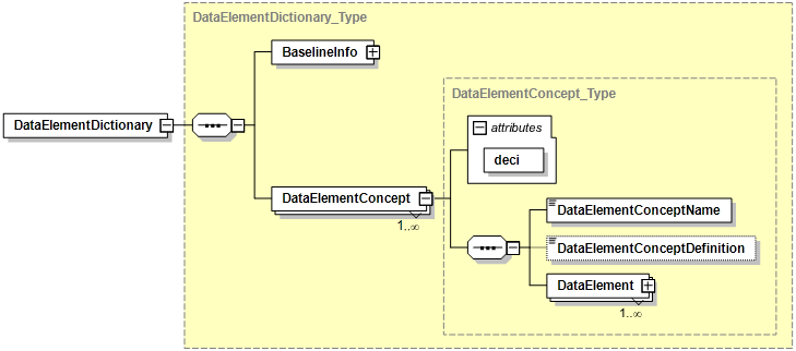
359. The base DataElementDictionary XML Schema provides the common elements used for capturing the Data Elements. These common elements are depicted in Figure A.13 followed by a short description.
-
DataElementDictionary: Denotes the top level element containing the Data Element Dictionary for the specific Information Exchange as defined in the BaselineInfo element.
-
BaselineInfo: Contains the meta-data for this STANAG like its title, identifier, version, security markings, etc. and is further described below.
-
DataElementConcept: Describes a Data Element Concept which includes a single concept and is the generic representation of the Data Elements grouped under it.
-
DataElement: Describes a Data Element, which is a representative of the corresponding Data Element Concept. It is further described in the section below.
The example below depicts the top-level elements of the XML instance document of the Data Element Dictionary for STANAG 5516 Ed6 showing the root element, the BaselineInfo details (explained in the next section) and one of the DataElementConcepts.
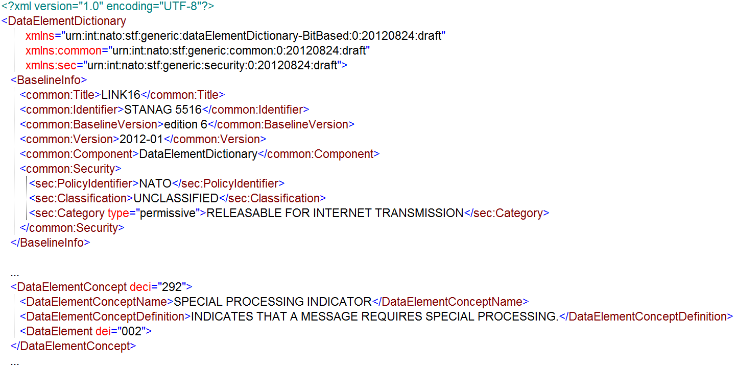 Figure A.14. Example of Data Element Dictionary XML instance for Link 16
A.5.5.4.8. BaselineInfo XML Schema
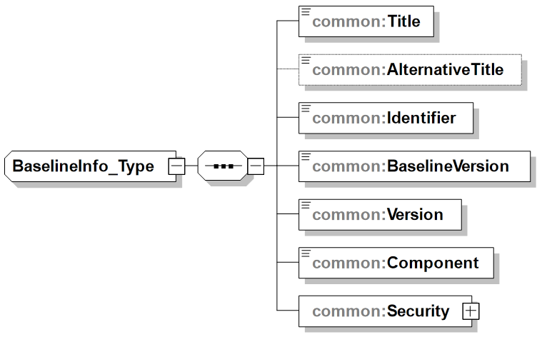
360. The BaselineInfo element is further detailed in Figure A.15 followed by a short description of its main elements.
-
Title: Provides the name given to the STANAG as Configuration Item (CI). Enables the user to find the CI with a particular title or carry out more accurate searches. The title is commonly used as the key point of reference in the list of search results. Examples are "TACTICAL DATA EXCHANGE - LINK 16" and "NATO IMPLEMENTATION CODES AND RULES".
-
AlternativeTitle: Provides any form of the title used as a substitute or alternative to the formal title of the Configuration Item (CI). Examples are "Link16 spec" and "NICR".
-
Identifier: Provides an unambiguous reference to the STANAG as Configuration Item (CI) within the context of specific community. An internal, external, and/or universal identification number for a data asset or resource. Examples are "STANAG 5516", "ADatP-31" and "NICR T/1".
-
BaselineVersion: Provides the edition or version of the STANAG as Configuration Item. Examples are "edition 5" and "edition 6, first draft".
-
Version: Provides the internal version number of the instance document.
-
Component: Identifies the STF component of the specification that this instance document contains. This element explicitly indicates what is implied by the root element to support discovery. Examples are "MessageStructure" and "DataElementDictionary".
-
Security: Contains the security markings for the instance document (i.e. the specification) and is further described in the next section.
See the section above on the Base DataElementDictionary for an example of the usage of the BaselineInfo element.
A.5.5.4.9. Security XML Schema
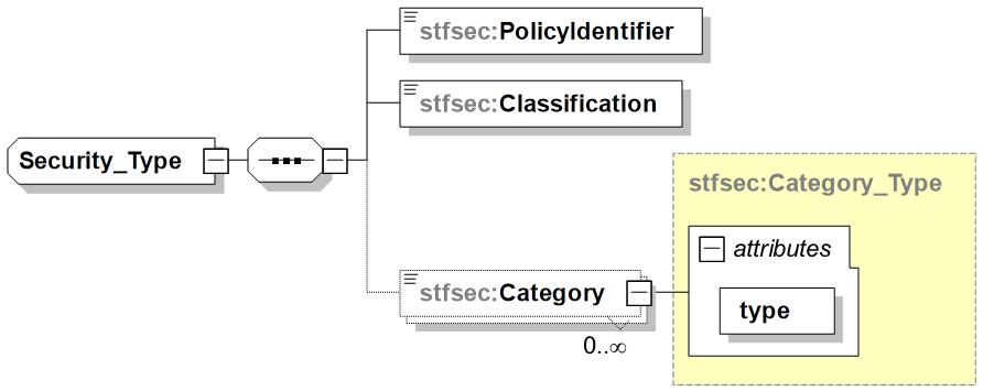
361. The Security element provides specific Information Assurance (IA) metadata for data objects; supports typical existing security labels to express policy, classification and category attributes. It is depicted in Figure A.16 followed by a short description of its main elements.
-
PolicyIdentifier: Identifies the nation or organization responsible for creating, maintaining, and implementing the security policy to be applied to the information. The security policy is understood as a set of rules for protecting information against unauthorized discloser, while maintaining authorised access, and preventing loss of unauthorized modification. The policy bodies of different security domains must agree on a common understanding of the handling requirements for information of a particular sensitivity. After the understanding exists, mappings from one security policy to another can be created (see Reference EAPC(AC/322-SC/5)N(2006)0008). For example, NATO, NATO/EAPC, NATO/PFP, NATO/EU, NATO/RUSSIA, NATO/UKRAINE. National use includes: USA, FRA, GBR, NLD, etc.
-
Classification: Provides security markings that indicate the sensitivity level of the information (see Reference : EAPC(AC/322-SC/5)N(2006)0008). Examples as defined in AC/322-D(2004)0021 and in "Guidance on the use of metadata element descriptions for use in NDMS" are UNMARKED, UNCLASSIFIED, RESTRICTED, CONFIDENTIAL, SECRET, and COSMIC TOP SECRET.
-
Category: Provides an indication of an additional, specific sensitivity, or a dissemination control, or an informational marking on which no automated access control is performed (see Reference : EAPC(AC/322-SC/5)N(2006)0008). Special category designator include ATOMAL, CRYPTO, SIOP, SIOP ESI. Dissemination Limitation Markings include EXCLUSIVE, INTELLIGENCE, LOGISTICS, OPERATIONS. Release categories include RELEASABLE TO, RELEASABLE FOR (e.g. RELEASABLE TO ISAF or RELEASABLE FOR INTERNET TRANSMISSION). Administrative markings include MANAGEMENT, STAFF, PERSONAL, MEDICAL, COMMERCIAL.
-
type (attribute for Category): Can be one of permissive, restrictive or informational.
See the section above on the Base DataElementDictionary for an example of the usage of the Security element.
A.5.5.4.10. DataElement XML Schema
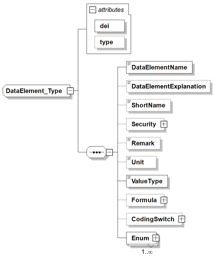
362. The DataElement XML element describes a Data Element, which is a representative of the corresponding Data Element Concept. It denotes the actual Data Element and contains the Data Items (DIs) used to compose the Data Element. The combination of a Data Element Concept Identifier (deci) and a Data Element Identifier (dei) uniquely defines a Data Element. The DataElement XML element is depicted in Figure A.17 followed by a short description of its main elements.
-
DataElementName: Provides the name of this Data Element.
-
dei (attribute of DataElement): Specifies the Data Element Identifier, which needs to be unique within the parent Data Element Concept.
-
type (attribute of DataElement): Provides a mechanism to differentiate between types of Data Elements, for example data elements used as spare, disused ones, required for the structure of a message, or holding actual data. The following values are currently supported by STF:
DataElement type Meaning spare Indicates this Data Element denotes a spare; a data element that, on transmissions, will be encoded as zero and shall not be processed upon receipt. Messages shall not be discarded upon receipt of non-zero spare fields. disused Indicates this Data Element denotes a disused element which are spare fields that previously had a valid meaning. When transmitted, Disused fields shall be encoded as 0 and shall not be processed upon receipt. Messages shall not be discarded upon receipt of a nonzero Disused field. structure Indicates this Data Element is used to define the structure of a message or word. This includes Data Elements that define which message or word is handled (e.g. for the message label) or Data Elements that act purely as a structure switch and do not itself represent any information. data Indicates this Data Element is carying real (tactical) data. -
DataElementExplanation: Provides an explanation of how to use this Data Element
-
ShortName: Provides a short version of the DataElementName, which can be used to refer to the DataElement. It is aimed to make this ShortName unique over all Data Elements, but this cannot be guaranteed at this time.
-
Security: Provides the ability to provide additional security markings for the DataElement. If none is specified it takes the security markings from the BaselineInfo.
-
Remark: Provides an optional remark for this Data Element specification.
-
Unit: Specifies the measurement unit for this Data Element, e.g. Meters, Degrees, Feet. The possible units are specific for a STANAG although preferably units should be used that are defined in standards. If no unit is specified, the value is without unit which is true for all pure enumerations. If the coding for this Data Element utilises a CodingSwitch (i.e. the coding depends on the value of another Data Field), the unit can be different for different coding variants. In that case the Unit should be specified within the CodingSwitch.
-
ValueType: Specifies the specific type of value that is represented, e.g. Double, Integer or Enumeration. The current list of types can be extended if required. If the coding for this Data Element utilizes a CodingSwitch (i.e. the coding depends on the value of another Data Field), the value type can also be different for different coding variants. In that case the ValueType should be specified within the CodingSwitch.
-
Formula: Specifies the Formula needed to decode the decimal value to a meaningful value of a Data Element
-
CodingSwitch: Defines a decoding switch indicating that, based on the value of the referenced DataField, this DataElement needs to be decoded in a certain way. E.g. the referenced DataElement specifies that this DataElement needs to be interpreted as an altitude in either 1 meter, 10 meters or 100 meters increment.
-
Enum: Defines a mapping from the exchanged value in a message to its meaning. Mappings can be provided to text (e.g. the reported numerical value 3 means FRIEND, or the reported textual value SV means Surface Vessel), or to the real, meaningful value (e.g. reporting the binary latitude as a double). In case the mapping to a meaningful value is provided, normally not all possible values are enumerated but instead the mapping from a range of binary values to a range of meaningful values (e.g. "0 through 2047" maps to "0 through 511 3/4 data miles"). The enumeration element provides information to encode and decode the exchanged value to a meaningful value for processing or to present as human-readable information. The CodingSwitch and Enum elements are further detailed below.
The example below depicts two examples of the representation of a Data Element, one for a bit-based Data Element from STANAG 5516 Ed6 and one for a text-based Data Element from STANAG 5500.
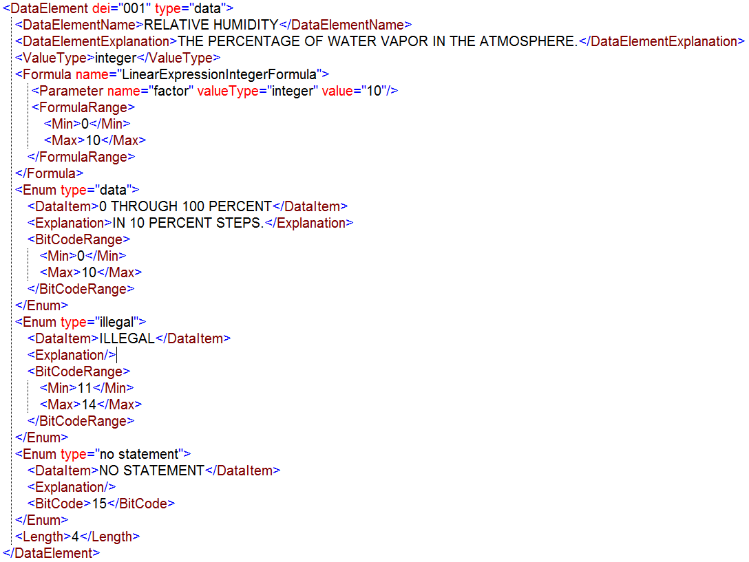 Figure A.18. Example of DataElement XML instance for Link 16
The above example demomstrates how the various elements can be used for a bit-based data element that represent a numerical value (see ValueType element). Note that the Formula that produces the meaningful value for this Data Element only is valid for a specific range of the raw value. The remaining values (so 11..14 and 15) are only valid as enumerations.
The logic of the actual formula is not covered by the STF yet, although a limited number of formulas can be defined, each with its own explicit semantics. In this case, the LinearExpressionIntegerFormula will produce a meaningful value by taking two parameters, offset and factor, and applying the formula: meaningful-value = exchanged-value * factor + offset The definition of the formulas is under discussion and will be considered for the next version of the STF.
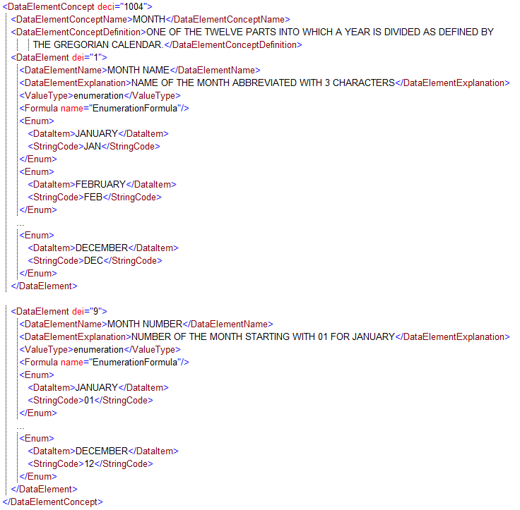 Figure A.19. Example of DataElement XML instance for ADatP-3
The above example demonstrates the use of the Enum elements for pure mappings, in this case for a text-based format. For the first Data Element, the exchanged value of JAN is decoded as JANUARY, while for the second Data Element, the values are encoded as numbers starting with 01 for JANUARY.
A.5.5.4.11. DataElement Enum XML Schema
363. The Enum XML element defines a mapping from the actual value as exchanged in a message to its meaning. It is depicted in Figure A.20 followed by a short description of its main elements.
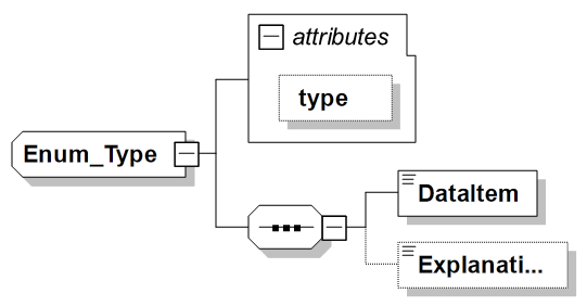
364. The XML Schema does not cover the aspect of the exchanged value as this mapping depends on the type of exchange (bit-based vs. text-based) and therefore the way to describe the exchanged value is type specific and is described in the respective sections.
-
type (attribute): Provides a mechanism to differentiate between types of Data Items, i.e. values, to further support automated interpretation. Currently the following types are supported:
Enum type Meaning disused Indicates a Data Item value that was previously named but is no longer valid. A DISUSED value cannot be renamed without determining if coordinated implementation is required. undefined Indicates a term used to describe a code that has no value currently assigned but may have a value assigned in the future. (This occurs in logically coded Data Elements in which all the Data Items in the Data Element do not have assigned values.) illegal Indicates a term used to describe a code that is not a permissible entry into the tactical data system(s) supporting the interface, e.g., a 9 bit Data Element called HEADING that has legal values of 0 through 359 representing degrees has illegal values of 360 through 511. no statement Indicates no information on this Data Element is being transmitted. (This does not necessarily indicate that the originator does not have the information.) unknown Indicates other values available for this Data Element have not been determined by the originator. to be determined Indicates that Data Item design is incomplete. (Data Items and codes will be specified at a later time.) data Indicates actual data. reserved Indicates that this value is reserved for future use. -
DataItem: Provides the description and/or decoded value of this enumeration.
-
Explanation: Provides an additional explanation for this Data Item only when necessary for amplification.
See the DataElement example above for examples on Enums, both for bit-based and for text-based information exchanges.
A.5.5.4.12. DataElement CodingSwitch XML Schema
365. The CodingSwitch XML element provides a way to specify that the encoding/decoding of a DataElement depends on the value of another DataElement. For example, an Altitude DataElement has a value of 5 which means an actual altitude of either 5 meter or 50 meter, indicated by the value of an Altitude Scale Indicator DataElement. Such a construct is typically used within bit-based information exchanges for space efficiency. Note that the CodingSwitch can be nested for the situation where the coding is dependent on multiple data elements.
366. The CodingSwitch XML element is depicted in Figure A.21 followed by a short description of its main elements.
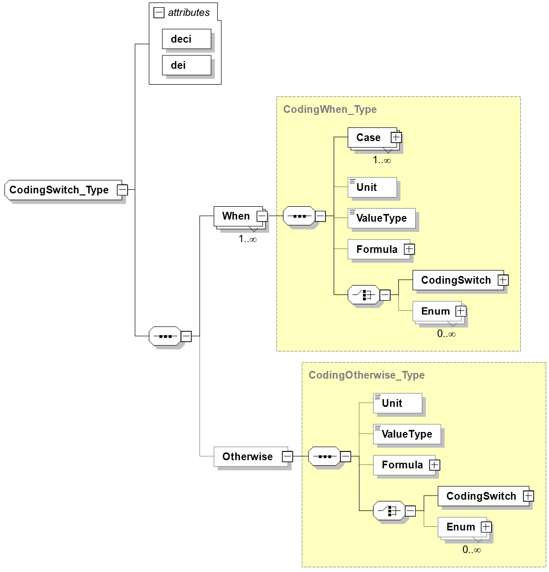
-
deci and dei: Indicates the Data Element Concept Identifier (deci) and Data Element Identifier (dei) of the referenced, controlling DataField in the message context whose value is used to switch on.
-
When: Encapsulates a specific coding for the DataElement. The enclosed Case element(s) indicate for which value(s) of the referenced DataField this coding should be chosen.
-
Otherwise: Encapsulates a specific coding for the DataElement which is chosen if none of the When branches is selected.
-
Case: Defines for which value a specific coding applies. This is either indicated with a single value or a range of values, the specifics of which are defined in the type-specific XSD (i.e. bit-based or text-based).
-
Unit, ValueType, Formula, Enum: as defined for the DataElement. Their presence within the CodingSwitch will overrule any definition provided at a higher level in the DataElement.
367. The example below for the DEPTH Data Element of STANAG 5516 demonstrates the use of a CodingSwitch where the actual depth is depending of the value of another DataElement that is indicating the multiplication factor.
  <DataElementConcept deci="366">
     <DataElementConceptName>DEPTH</DataElementConceptName>
     <DataElementConceptDefinition>USED TO REPORT DEPTH IN
        METERS OR A PLAIN STATEMENT.
     </DataElementConceptDefinition>
     <DataElement dei="013">
        <DataElementName>DEPTH, TRANSDUCER</DataElementName>
        <DataElementExplanation>WHEN MULTIPLIED BY DEPTH
        INDICATOR (SONOBUOY), EXPRESSES DEPTH OF SONOBUOY
	TRANSDUCER AS MEASURED DOWNWARD FROM MSL AS A
	POSITIVE QUANTITY IN METERS.  INTERPRETED ONLY WHEN
	DEPTH INDICATOR (SONOBUOY) IS  NOT SET TO ZERO.
	</DataElementExplanation>
        <ValueType>Enumeration</ValueType>
        <Formula name="EnumerationFormula"/>
        <CodingSwitch deci="366" dei="012">
		<!-- DEPTH INDICATOR (SONOBUOY) -->
           <When>
              <Case value="0"/>
              <ValueType>Enumeration</ValueType>
              <Formula name="EnumerationFormula"/>
              <Enum type="inconsistency">
                 <DataItem>INCONSISTENCY</DataItem>
                 <Explanation>CANNOT DECODE THIS COMBINATION
		 OF DFI/DUI VALUE(S) AND STRUCTURE-SWITCH
		 VALUE(S)</Explanation>
                 <BitCodeRange><Min>0</Min><Max>15</Max>
                 </BitCodeRange>
              </Enum>
           </When>
           <When>
              <Case value="1"/>
              <Unit>METER</Unit>
              <ValueType>Integer</ValueType>
              <Formula name="LinearExpressionIntegerFormula">
                 <Parameter name="factor"
		 valueType="Enumeration" value="3"/>
                 <FormulaRange><Min>1</Min><Max>9</Max>
                 </FormulaRange>
              </Formula>
              <Enum type="no statement">
                 <DataItem>NO STATEMENT</DataItem>
                 <Explanation/>
                 <BitCode>0</BitCode>
              </Enum>
              <Enum type="data">
                 <DataItem>DEPTH (METERS X DEPTH INDICATOR)
		 </DataItem>
                 <Explanation/>
                 <BitCodeRange><Min>1</Min><Max>9</Max>
                 </BitCodeRange>
              </Enum>
              <Enum type="undefined">
                 <DataItem>UNDEFINED</DataItem>
                 <Explanation/>
                 <BitCodeRange><Min>10</Min><Max>15</Max>
                 </BitCodeRange>
              </Enum>
           </When>
           <When>
              <Case value="2"/>
              <Unit>METER</Unit>
              <ValueType>Integer</ValueType>
              <Formula name="LinearExpressionIntegerFormula">
                 <Parameter name="factor"
		 valueType="Enumeration" value="30"/>
                 <FormulaRange><Min>1</Min><Max>9</Max>
                 </FormulaRange>
              </Formula>
              <Enum type="no statement">
                 <DataItem>NO STATEMENT</DataItem>
                 <Explanation/>
                 <BitCode>0</BitCode>
              </Enum>
              <Enum type="data">
                 <DataItem>DEPTH (METERS X DEPTH INDICATOR)
		 </DataItem>
                 <Explanation/>
                 <BitCodeRange><Min>1</Min><Max>9</Max>
                 </BitCodeRange>
              </Enum>
              <Enum type="undefined">
                 <DataItem>UNDEFINED</DataItem>
                 <Explanation/>
                 <BitCodeRange><Min>10</Min><Max>15</Max>
                 </BitCodeRange>
              </Enum>
           </When>
           <When>
              <Case value="3"/>
              <Unit>METER</Unit>
              <ValueType>Integer</ValueType>
              <Formula name="LinearExpressionIntegerFormula">
                 <Parameter name="factor"
			valueType="Enumeration"
			value="300"/>
                 <FormulaRange><Min>1</Min><Max>9</Max>
                 </FormulaRange>
              </Formula>
              <Enum type="no statement">
                 <DataItem>NO STATEMENT</DataItem>
                 <Explanation/>
                 <BitCode>0</BitCode>
              </Enum>
              <Enum type="data">
                 <DataItem>DEPTH (METERS X DEPTH INDICATOR)
		 </DataItem>
                 <Explanation/>
                 <BitCodeRange><Min>1</Min><Max>9</Max>
                 </BitCodeRange>
              </Enum>
              <Enum type="undefined">
                 <DataItem>UNDEFINED</DataItem>
                 <Explanation/>
                 <BitCodeRange><Min>10</Min><Max>15</Max>
                 </BitCodeRange>
              </Enum>
           </When>
        </CodingSwitch>
        <Length>4</Length>
     </DataElement>
  </DataElementConcept>
A.5.5.4.13. Bit-based Data Element Dictionary XML Schema
368. The XML Schema for BitBased Data Element Dictionary extends the base Data Element Dictionary XML Schema with the additional information required to capture bit-based Data Elements. In particular, it adds the following:
-
Length element to the DataElement element expressed in number of bits
-
BitCoding element to the DataElement element indicating how numerical values are encoded. Possible values are unsigned, onesComplement, twosComplement, modifiedTwosComplement, and signMagnitude.
-
BitCode element as sub-element of the Enum element. Holds the actual numerical value which can be mapped to its meaning held in DataItem.
-
BitCodeRange element as sub-element of the Enum element. Similar to the BitCode element but provides a range of actual values instead.
369. The examples shown before demonstrate the use of these additional elements.
A.5.5.4.14. Structured Text-based Data Element Dictionary XML Schema
370. The XML Schema for text-based Data Element Dictionary extends the base Data Element Dictionary XML Schema with the additional information required to capture text-based Data Elements. In particular, it adds the following:
-
CharacterSet attribute to the DataElement element indicating which characters are allowed in the actual value, e.g. only uppercase alphabetical characters, or only digits. If unspecified, any character is allowed although e.g. for Field or Word separation, specific messages might be excluded.
-
RegularExpression attribute to the DataElement element indicating alone or in addition to the CharacterSet the restriction on the actual value of the DataElement by specifying a regular expression, e.g. "[0-9]{3,6}[A-Z]" indicating 3 to 6 digits followed by one uppercase alphabetical character.
-
MinimumLength and MaximumLength attributes to the DataElement element indicating the minimum and maximum allowed length of the actual value. If unspecified, MinimumLength is interpreted as 0 and MaximumLength as unbounded, although the message or transport might impose a maximum.
-
StringCode element as sub-element of the Enum element. Holds the actual textual value which can be mapped to its meaning held in DataItem.
371. The examples shown before demonstrate the use of these additional elements.
A.5.5.4.15. XML-based Data Element Dictionary XML Schema
372. Not yet addressed within the current version of the STF.
A.5.5.5. Message Structure Layer Design Rules & Methodology
A.5.5.5.1. Message Structure Concepts
-
Data Field: The instantiation or use of a data element.
-
Word: A structured collection, or container, of one or more data fields used to report on a specific aspect.
-
For example, in ADatP-3, within the OWNSITREP message, the LOCATION set provides the Geographic Location of the unit and the LOCAMPN set provides Location Amplification, while in Link-16, within the J3.1 message, the J3.1I word reports on the basic information for an emergency point and J3.1C1 provides the IFF/SIF codes.
-
Message: A structured collection of one or more words to report a particular set of information.
-
For example, the ADatP-3 OWNSITREP message for reporting information regarding own and subordinate units can contain nested sets including the LOCATION and LOCAMPN sets, while the Link-16 J3.2 message for reporting (the state of) an air track can contain the J3.2I, J3.2E0, and J3.2C1 words.
-
StructureSwitch: Similar to the concept of a "switch" statement in computer programming, a StructureSwitch is a "conditional construct" that is used as a way to select between alternative data sets within a message structure. It allows for building message structures where the value of a data field defines which following data field(s) are included in the message. StructureSwitches can be nested to support multiple levels of data set selection.
-
Within the TDL and JISR community, this would be considered as overlaid sets of data fields, where the value of another, referenced data field, defines which set is present in a word. For example, if in the Link-16 J7.0 message the environment/category data field indicates AIR then the word contains the Air Platform and the Air Platform Activity data fields, while for the GMTI format, if the Segment Type data field specifies Mission Segment the following data is containing the data fields like Mission Plan and Flight Plan.
-
Data Element Dictionary: The collection of all Data Elements used in the Messages specified by this information exchange STANAG.
-
A.5.5.5.2. Message Structure Logical Model
373. This logical model shows the relationship between these concepts to support the definition of a generic information exchange message structure. The attributes shown in the classes denote relevant information that needs to be captured on the classes or indicate a relationship between classes (e.g. dui).
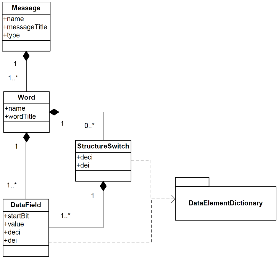
374. The Message Structure XML Schemas are derived from this logical model, fully elaborated to include all components (elements and attributes) that are required to model the generic message structures for all types of information exchanges.
A.5.5.5.3. Known Limitations
375. There are some known shortcomings in Version 1.0 of the STF Message Structure XML Schemas and Logical Model in supporting all types of information exchange message structures. These are described here:
-
Information exchange specifications sometimes do not specify a container-like construct such as the "word" concept defined here. Instead, they define messages as a flat collection of data elements.
-
Messages with a more complex structure cannot be represented with the current Message / Word / DataField structure. For example, VMF or the encapsulating protocol for Link 22 messages require more nesting support, such as nesting Words within other Word containers, to get "Sets", "Segments", etc.
-
The current structure does not yet support information exchange specifications that define messages of variable length by including optional contents (e.g. VMF, GMTI, DIS, ASTERIX), but will be enhanced to serve this purpose.
-
Further details need to be captured in XML on how the data is serialised, e.g. big-endian vs. little-endian, bit-order, character coding.
These are being considered, and extensions, such as the ability to have nested Word elements, to the current model to address these limitations will be provided in Version 2.0 of the STF Design Rules.
A.5.5.5.4. Message Structure Design Rules
376. Based on the type of information exchange specified by the IES, a specific adapter (extension) of the common STF Message Structure XML Schema (STFMessageStructure-*.xsd) shall be used to capture the Message Structures supporting that information exchange in an XML representation to fulfil the Message Structure layer of the STF, as depicted in Figure A.23.
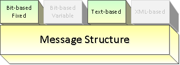
377. Below are the design rules with the methodology on how to apply them to create the XML file to capture the message structures for a particular information exchange:
378. Rule 1: The MessageStructure-BitBasedFixedLength.xsd shall be applied in case the Information Exchange is bit-based and the Message Structure type defines messages of fixed length, i.e. no presence of optional contents and use of filler bits.
379. Rule 2: (Future work) -The MessageStructure-BitBasedVariableLength.xsd shall be applied in case the Information Exchange is bit-based and the Message Structure type defines messages of variable length, i.e. presence of optional contents.
380. This XSD is not provided within the current version of the STF.
381. Rule 3: The MessageStructure-TextBased.xsd shall be applied in case the Information Exchange is text-based and the Message Structure type is non-XML.
382. Rule 4: (Future work) - The MessageStructure-XMLBased.xsd shall be applied in case the Information Exchange is based on XML. This will capture the Container Elements for each message. The message structure itself is provided by the XSD as defined in the STANAG. The MessageStructure-XMLBased.xsd defines the mapping between the STF Container Elements and the corresponding XSD constructs (e.g. xsd:group, xsd:sequence). This XSD is not provided within the current version of the STF.
A.5.5.5.5. Methodology for Message Structure Definition
383. Step 1: Determine which type of message exchange (bit-based fixed length, bit-based variable length, text-based or XML-based). Based on this, determine the correct STF XML artefact to use and the XML namespace to use for the MS XML instance document that will be created to define the information exchange message structures. Bit-based, text-based and XML-based types each have their own XML namespace.
384. Step 2: Identify all messages to be exchanged.
385. Step 3: For each message, identify the grouping constructs. Depending on the format, terms like word, group, set, container, segment, PDU, etc. may be used.
386. Step 4: For all identified grouping constructs, determine how they should be mapped to the 'Word' abstract concept in the STF MS XML Schema. The mapping does not need to be one-to-one. For example, extra words may be added if they are necessary to group repeated fields even though the specification of the format does not group them.
387. Step 5: For each message, determine the data fields that make up the message using data elements captured within the STANAG-specific DED XML from Section A.5.5.4.
388. Step 5a: If there is a need within a particular message for a StructureSwitch, then for each "switch" pattern, determine the conditions that control the switch.
389. Step 6: Identify all properties of the messages, groupings (words) and data fields, such as DECI and DEI number, name, title, purpose, remarks, start bits if appropriate, fixed and value.
390. Step 7: Create the XML instance document representing the MS, according to the appropriate XML Schema selected in Step 1.
A.5.5.5.6. Description of the Message Structure XML Schema Definitions
391. The following sections describe the XML Schema definitions used to capture the Message Structure.
A.5.5.5.7. Base Message Structure XML Schema
392. The base Message Structure XML Schema provides the common elements used for capturing the Message Structure. These common elements are depicted in Figure A.24 followed by a short description.
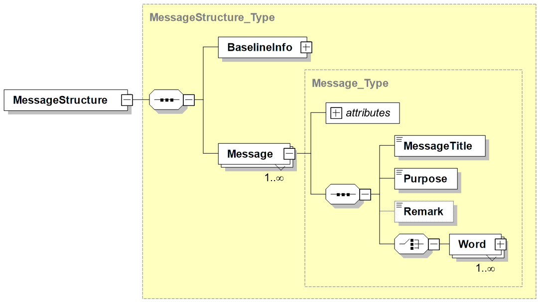
-
MessageStructure: Denotes the top level element containing the definition of the structure of the messages for a specific STANAG as defined in the BaselineInfo element.
-
BaselineInfo: See the section on BaselineInfo XML Schema within the description of the DED XML Schema Definitions
-
Message: Defines the structure information for a particular Message. A Message has some metadata (like a Name and Title) and consists of Word elements.
-
Word: Defines the possible Words that are defined for this Message which acts as a container for the actual DataFields. The presence or order of the Words within an exchanged Message is not prescribed here.
The Word element is further detailed in the section below followed by a short description of its main elements.
The example in Figure A.25 depicts the top-level elements of the XML instance document of the Message Structure for STANAG 5516 Ed6 showing the root element, the BaselineInfo details (explained before) and one of the Messages.
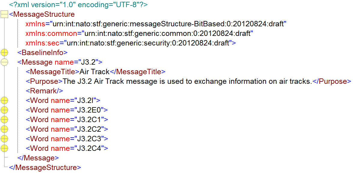 Figure A.25. Word XML Schema
A.5.5.5.8. Word XML Schema
393. The structure of the Word element is shown in Figure A.26 followed by a short description of its main elements.
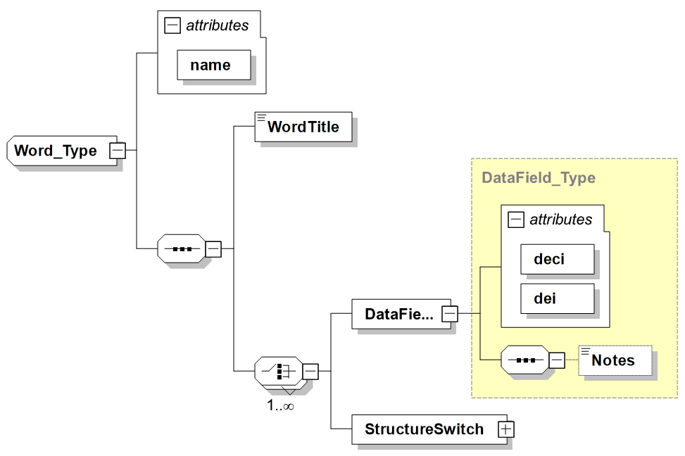
-
name (attribute): Specifies the name of the Word including specific characters and/or spaces.
-
WordTitle: Specifies the title of the Word.
-
DataField: Describes a DataField within a Word holding the actual data. A DataField refers to a Data Element via the deci and dei. The order of the DataFields within a Word is relevant. Optionally a DataField can have a fixed value.
-
StructureSwitch: Defines a "conditional construct" that is used as a way to select between alternative data sets within a message structure. Based on the value of the referenced DataField one of a set of DataFields is expected. E.g. depending on the value of DataField 'Environment Category' (Air, Ground, Surface, etc), either the 'Air platform', 'Ground platform', 'Surface platform', etc. DataField is present. The StructureSwitch element is built from one or more 'When' entries and an optional 'Otherwise' entry each holding one or more DataFields and/or nested StructureSwitch elements.
The figures below depict examples of the representation of a bit-based Word from STANAG 5516 Ed6, and a text-based Message and 2 Words for OTH Gold.
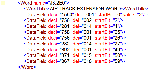 Figure A.27. Example of Word XML instance for Link 16
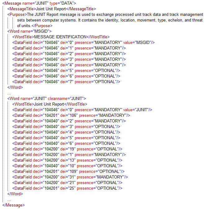 Figure A.28. Example of Message and 2 Words XML instance for OTH Gold
A.5.5.5.9. StructureSwitch XML Schema
394. The structure of the StructureSwitch element is shown in Figure A.29 followed by a short description of its main elements.
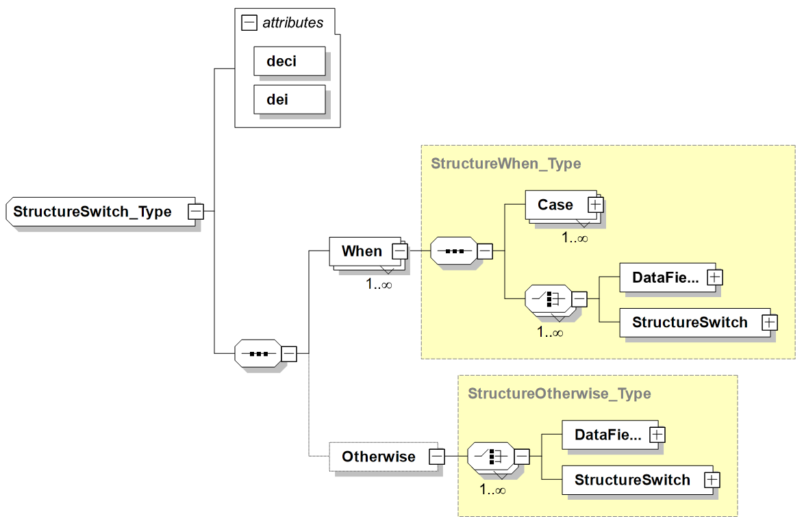
-
deci and dei (attributes): Indicate the deci and dei numbers of the referenced DataField that is the base of the StructureSwitch. Based on the value of te referenced DataField one of the When blocks applies or alternatively the Otherwise.
-
When: Defines an alternative set of one or more DataField(s) or nested StructureSwitch(es). The enclosed Case element(s) indicate for which value(s) of the referenced DataField this set should be chosen..
-
Otherwise: Defines the alternative set of one or more DataField(s) or nested StructureSwitch(es) in case none of the preceding When elements was applied (i.e. none of the indicated Case elements).
-
Case: Specifies the value for the referenced DataField for which the enclosing When element is selected and therefore the following DataField(s) and/or nested StructureSwitch(es). The value is either indicated with a single value or a range of values, the specifics of which are defined in the type-specific XSD (i.e. bit-based or text-based). Note that a When element can contain multiple Case elements to be able to specify that this When applies for all the specified values.
The example below depicts an example of the representation of a StructureSwitch from STANAG 5516 Ed6. The example specifies that after DataField 758/004, different DataFields can occur depending on the value of the DataField 385/003. If its value is 0, then the DataField will be 376/007, while if the value is 1, the DataField will be 376/001. Taking the definitions of these DataElements from STANAG 5516 Ed6 into account, this means that the EXERCISE INDICATOR field controls whether the field is interpreted as either the IDENTITY field or the IDENTITY AMPLIFYING DESCRIPTOR.
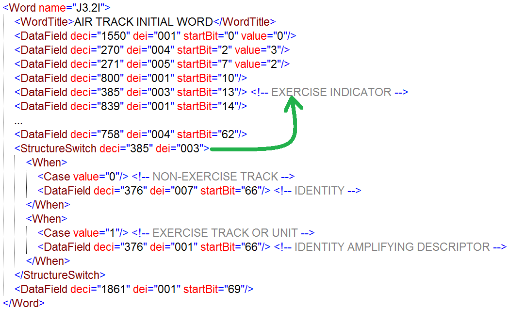 Figure A.30. Bit-based Message Structure XML Schema
A.5.5.5.10. Bit-based Message Structure XML Schema
395. The XML Schema for BitBased Message Structure extends the base Message Structure XML Schema with the additional information required to capture bit-based Message Structures. In particular, it adds the following:
-
startBit attribute to the DataField element expressed as offset in number of bits from 0.
-
Optional value attribute to the DataField element for holding the fixed value as an unsigned decimal.
-
Decimal value attribute of the Case element within the StructureSwitch.
396. The examples shown before demonstrate the use of these additional elements.
A.5.5.5.11. Structured text-based Message Structure XML Schema
397. The XML Schema for Structured Text-based messages extends the base Message Structure XML Schema with the additional information required to capture text-based Message Structures. In particular, it adds the following:
-
Optional value attribute to the DataField element for holding the fixed value as a string.
-
String value attribute of the Case element within the StructureSwitch.
-
Optional presence attribute to the DataField element to indicate whether an actual value is optional or mandatory.
398. The examples shown before demonstrate the use of these additional elements.
A.5.5.5.12. XML-based Message Structure XML Schema
399. Not yet addressed within the current version of the STF.
A.5.5.6. Business Rules Design Rules & Methodology
400. Not yet addressed within the current version of the STF.
A.5.5.7. Security Cross-Domain Design Rules & Methodology
401. Not yet addressed within the current version of the STF.
A.5.5.8. Web Services Design Rules & Methodology
402. Not yet addressed within the current version of the STF.
A.5.5.9. Operational Cross-Domain Design Rules & Methodology
403. Not yet addressed within the current version of the STF.
A.5.6. Consequences
404. To fulfil the information exchange requirements from a mid and a long term view it is essential to plan the implementation of the guidance from a holistic approach. This means the approach needs to achieve improvements which are both efficient and effective. The approach should be modular to enable to re-use, while a spiral approach will allow for continual learning and improvement. The following key success factors for the STANAG transformation need to be considered.
A.5.6.1. Efficiency
405. The process of STANAG transformation should result in an improved efficiency from multiple perspectives. One of the main aspects of efficiency is to enhance the cost effectiveness by reducing manual labour. The reduction of manual labour will also provide an advantage by reducing time in STANAG development and maintenance. In particular, this will:
-
Lead towards faster implementation of Change Proposals (CP) to the STANAG.
-
Facilitate the discovery of ambiguities via automatic verification of both the STANAG and the CPs.
-
Cause a reduction in the need for the manual labour-intensive actions (validation, implementation, etc.).
A.5.6.2. Effectiveness
406. The process of transforming the STANAG towards machine readable STANAGs will increase effectiveness:
-
By enabling common interpretation of the standards via the non-ambiguous machine interpretable STANAGs.
-
Via the enabling of automated standard validation, in order to find possible errors at an earlier stage.
-
In the semi-automatic system implementation that are facilitated via the creation of machine interpretable STANAGs. This will reduce the human errors in the system implementation of the STANAGs and thus lead to better implementations.
-
In facilitating the semi-automatic validation of system implementation in order to find system failures at an earlier stage. This validation is supported by the STANAGs being machine readable.
-
By providing the possibility to generate system documentation in a semi-automated way, based on the machine interpretable STANAG. Allowing the system documentation and system implementation to be always in line for the STANAG implementation part.
-
In data harmonisation by aligning the machine interpretable STANAG to the Guidance for XML Naming and Design (GXND) and therefore enabling the registration in the NATO Metadata registry and Repository (NMRR) for data element harmonisation and vocabulary management.
A.5.6.3. Modularity
407. The STANAG transformation process aims to result into a modular machine interpretable STANAG, which will provide the following advantages compared to the current STANAGs:
-
Different modules within the STANAG can be reused within other STANAGs.
-
The components must be derived from the requirements of the different scenarios. Nevertheless, after the transformation of the STANAG, it can be applied based on the context. E.g. if no security context is needed, the security layer can be either not implemented or disabled in specific situations
-
Using the modular approach in the STANAG and addressing all different aspects will make the STANAG ready to fulfil unforeseen requirements.
A.5.6.4. Spiral development
408. The Spiral development will enable the COI to achieve tangible results by adopting early technologies and concepts and learn from their application. This will provide operational and administrative benefits since the first deliverable and lessons learned and feedback can be retrofitted to the administrative community.
409. All consequences of implementing and not implementing a solution whether direct or indirect, wanted or unwanted shall be documented to the extent possible. Consequences for at least the following areas shall be regarded:
-
Time
-
Cost
-
Capabilities
-
Security
-
Interoperability
-
Usability
-
Flexibility
-
Procedures
A.5.6.5. Benefits of the layered approach
410. The use of the layered approach is a wide-spread and well-known concept that has been used for years and successful application can be found in the OSI reference model for communication protocols and semantic web interoperability. The adoption of this layered approach introduces multiple benefits:
-
Interoperability: Currently, solutions based on the standards attempt to provide the overall capability embedded in a single system due to the complexity and unclear separation between the different functional areas addressed by the STANAG. The ability to verify separate functionalities addressed by the current standards is minimal due to their unclear and tangled definitions. By untangling these functionalities and presenting them within a layered approach, the different functionalities can be verified layer by layer independently. This improves the quality of the standard and therefore contributes to overall interoperability.
-
Scalability: The means to accommodate unforeseen new requirements is enhanced by the application of the layered approach to the STANAG. A new layer can be introduced leveraging on the other layers in a controlled way, e.g. based on emerging requirements.
-
Flexibility: Each layer describes a specific functionality, where layers can be stacked on top of each other. When a specific functionality is not needed (e.g. Security cross-domain) for a specific deployment or system role, this approach allows clear identification of the parts of the STANAG that do not have to be implemented.
-
Maintainability: Without using a layered approach, identifying the impact of a change in one part of the STANAG to the other parts of the STANAG is often a challenge. Making changes to one of the layers in a layered approach will affect the other layers in a more controlled and traceable manner.
411. Therefore, the modular approach as adopted within the information exchange STANAG framework allows for maximum reuse of the STANAG layers and a more clear distinction between the different functionalities addressed within the STANAG.
A.5.6.6. Consequences of implementing the solution
412. Current and future operations require and will require interoperability at all levels: from machine-to-machine, to human-to-human via all the transformation steps from data to information. The essential pre-requisite is standardization and well-defined and error-free standards, which are machine-interpretable for ease of implementation and with no opportunity for mis-interpretation. Using the traditional approach to standardisation will continue to produce standards that are difficult to maintain and often contain errors, entail long delays before ratification, are ambiguous, and therefore result in non-interoperable systems. The new approach proposed in this document applies to five areas: The application of the layered approach, the configuration management of the standards, the development of systems, the actual interoperability, and the enhanced operational usage in the future. The benefits provided in each of these areas are further addressed in the following sections.
A.5.6.6.1. STANAG Configuration Management enhancements
413. The current configuration management (CM) of the various STANAGs is handled by their respective custodians (e.g. Defence Information Systems Agency (DISA) for STANAG 5516) using different proprietary tools and methodologies. The process of creating a new STANAG baseline is largely a manual task where changes to the STANAG text are applied to the proper sections; some of the text is maintained in a database as structured data (e.g. the Message Structure and Data Element Dictionary), others are maintained as a collection of plain text (e.g. the body text or the transmit and receive rules). Linkage between one baseline of a STANAG and a previous one is difficult. Furthermore, various STANAGs need to maintain consistency between them, e.g., those defining different Data Links and those that define the conversions between them, or STANAGs and standards which define common elements (e.g. positional definitions or identities (STANAG 1241)).
414. The CM process could leverage on the possibilities introduced by the representation of STANAGs in a machine-interpretable format which is structured and well-defined. Several enhancements are foreseen to the CM process:
-
More explicit specification of the components that make up a Configuration Item (CI) which makes these components easier to be discovered and referenced from other areas.
-
Automated support for creating a new baseline based on the availability in a machine-interpretable format of both the previous baseline and the changes to be applied.
-
Easier tracking of changes to the elements that make up the CI with all relevant aspects like what, when, why and who.
415. The machine-interpretable format of the STANAG can then be used to automatically generate the required STANAG documentation. The quality of this documentation will be greatly improved because of the resulting consistency in internal structure and phrasing, possible different views on the structure, fully hyperlinked to ease navigation, and support for different output formats (e.g. HTML, PDF, and Word). To support these enhancements, the improved standard would provide ways to create references on several levels that can be used:
-
Internally in a baseline, e.g., from the message structure to a data element or from the processing actions to a specific message.
-
From one baseline to previous ones, e.g. to trace changes to elements.
-
To other baselines of related standards, e.g., to data elements in a common or related standard (e.g. variable message format (VMF) and Link-22 re-use data elements from Link-16)).
416. Using these references, the internal and external integrity of the standard can then be validated resulting in increased quality of the produced baseline.
417. The actual changes in an information exchange standard are often part of a Change Proposal (CP) process. CPs are developed and then submitted by Nations and Strategic Commands (SC) represented in the body responsible for the CM of the STANAG in order to modify parts of the STANAGs. CPs could correct errors in the STANAGs or could introduce changes in order to implement new capabilities. As soon as agreement has been reached the CP and supplement sections will be embedded in the next edition of the STANAG.
418. This process could be greatly improved by having both CPs and STANAGs in a structured, well-defined, unambiguous, and machine-interpretable format [NC3A-TN-1391], resulting in the following benefits
-
Automated verification of impact and integrity constraints of the CP even before submission
-
Automated update of the STANAG based on the agreed CP, including automated referential integrity handling
-
Automated verification of changes to interoperability matrices as a result of the CP before agreement
-
Possibility to register the changed Information Exchange Specification in the NMRR in machine interpretable format for implementation
419. Several of the aforementioned baseline management activities are supported by the NATO Metadata Registry and Repository (NMRR), which is an NNEC core service for registration, discovery and configuration management of machine-interpretable artefacts. More information on the administrative aspects of the NMRR can be found in [NC3A-TN-1311] [NC3A-TN-1312] [NC3A-TN-1313] [RTO-EN-IST-088]. Besides being visible and accessible to human users, the artefacts registered in the NMRR will also be available to automated clients via a service interface. Due to the machine-interpretable format, services can make use of these artefacts and be notified of changes, thus enabling various advanced use cases. More information on these so-called `operational' aspects of the NMRR can be found in [NC3A-TN-1367] [NC3A-TN-1368] [NC3A-TN-1369].
A.5.6.6.2. STANAG Implementation & System development enhancement
420. A structured, well-defined, machine-interpretable standard can be used in various ways. Generation of human readable documentation is one of the most self-evident ones, which could also provide more capabilities than the current human readable standard by using the information provided by the structure. But because of the machine-interpretable aspect of the new specification, it's strength is most prominent when it is used as the base for the implementing system's logic i.e., using the specification to generate the system's implementation. In traditional systems, humans read the standard and implement the desired functionality. This is manual work to a large extent without real support for automation. Often engineers will convert certain aspects of the standard to some sort of structured information but each group is basically reinventing the wheel. Furthermore, besides being time-consuming and error-prone, it also requires the human to interpret thousands of pages of text, not always in their native language, while keeping track of the intrinsic linkage between the various sections of the standard. Undoubtedly each company or agency will have developed their own ways of tracking the quality of their work with linkage back to the specification which is a huge effort and therefore represents concrete value and is therefore not easily shared among companies or agencies.
421. Transforming the specification so it can be interpreted by a machine would mean a huge reduction of human interpretation. This can be achieved by defining only a limited and well-defined vocabulary instead of the many ways a natural language can be used to express, e.g., the logic of a system. Different ways of expressing the same thing might be pleasant while reading a novel but will trigger an engineer's brain to wonder whether the different wording might indicate a different behaviour. This is even more applicable when the language at hand is not the engineer's native language.
422. The reduction of human interpretation will have two aspects:
-
The level of interpretation will be reduced because of the limited and well-defined vocabulary: just a limited set of constructs needs to be defined with great accuracy and because there is only a limited set, it will be easier to understand.
-
The amount of interpretation will be reduced because, once the vocabulary is understood, the whole standard is basically about applying those constructs in a well-defined and repetitive way. That is obviously something a machine is aimed at.
423. When automatically generating systems, ruling out most of the human interpretation together with the increased power and quality of the specification, will have several positive effects on the resulting product:
-
Shorter time between specification and implementation: as the standard is now machine-interpretable there is no need to read through all the changes and then find and update the relevant code. In the best case it would be a push-on-a-button to create an updated system ready for testing.
-
Cost reduction: shorter time to implement an updated system has a direct impact on the costs. But furthermore, by generating parts of the system the time spent in testing can be reduced because mainly the generation process needs to be validated to produce the correct output.
-
Fewer errors: The machine-interpretable aspect means far less human interpretation is required and because of the automatic generation of part of the system less manual work needs to be performed. Both contribute to fewer errors in the final implementation of the system.
-
Improved interoperability: Using an unambiguous specification to produce an implementation of higher quality will increase the level of interoperability between systems. More on this subject is covered in the next section.
-
Test support: The specification can also be used during the test and validation phases of a system, e.g., to generate automatically test code and scenarios.
424. Obtaining all these benefits will obviously take time to mature but system development will be greatly enhanced resulting in better information exchange systems and increased interoperability which will further examined in the following section.
A.5.6.6.3. Interoperability enhancement
425. Assessment, verification and validation of the interoperability among platforms is essential in order to achieve situational awareness according to the NNEC Data Strategy. This is especially true in a NATO environment where various nations are collaborating with their own national systems, often developed by different companies and with different requirements. Interoperability shall be verified during various stages of the system's life, each of which can leverage on the machine-interpretable standard.
A.5.6.6.4. Paper based interoperability assessment
426. Originally, a paper-based interoperability assessment involved manually comparing documents against each other; the system's requirements document (SRD) or the interface control document (ICD) against the standard. By capturing the SRD and the ICD in XML in a similar manner to that foreseen for the TDL standard itself, automatic assessment of interoperability against the standard or another system can be easily achieved. This has a direct positive effect on both the quality of the comparison as well as the time it takes. The paper-based interoperability assessment between the SRD and the standard can be performed even before the system is actually built, reducing the costs associated with later changes. An example of such an interoperability assessment via machine interpretable versions of both the reference document and the ICD can be found in [REF-NC3A-NU/CCS/ADP/2008/331].
A.5.6.6.5. System development
427. Using the machine-interpretable standard to generate major parts of an implementation system, as explained in the previous section, will positively affect the level of interoperability between these systems. The level of interpretation is reduced because of the well-defined constructs and the limited number of constructs, while the amount of interpretation is reduced because of applying these constructs consistently over the whole standard. Furthermore, if a system interprets a certain construct in a non-standard way (i.e. a bug), this would affect all situations where it is applied which therefore increases the chance of discovering this during tests.
A.5.6.6.6. Interoperability testing
428. By using the machine-interpretable specification, not only can the system itself, but also test and analyzer tools can be generated to a large extent. The specification will contain all the information like the supported messages, their structure and the protocol for the message exchange. These tools can then be used to rigorously test systems against the standard, both in a one-on-one test and for analyzing the interaction between different systems.
A.5.6.6.7. Harmonisation of standards
429. The introduction of machine-interpretable standards will significantly increase the interoperability between systems whose implementation has been derived from the same standard; it will eliminate the need for ad-hoc interfaces and translation of data structures. To ensure interoperability between the systems based on different standards from different COIs, COIs should harmonise their information exchanges and establish common agreed upon operational cross-domain specifications. In the past, this process was often tedious for various reasons, but it is foreseen that this process can be facilitated by the application of the STF and the availability of the future NMRR capability to store and manage those specifications. More information about standardization, the power of metadata, such as the machine-interpretable standards, and the role of the NMRR, can be found in [NC3A-TN-1254] [RTO-EN-IST-088].
A.5.6.7. Consequences of not implementing the solution
430. The STF can be applied in several ways:
-
The STF Layered Framework is used to identify gaps in the IERs and IESs with respect to the NNEC Data Strategy goals.
-
The STF Layers are used to structure the evolution and development of IESs.
-
The STF Design Rules and XML artefacts are used to transform existing textual IES related to the message formats (DED and MS) into XML representations
431. If the STF is not applied in the evolution and development of IERs and IESs, there is a high risk that the following will occur:
-
IERs and IESs will be insufficiently specified, as developers may forget to consider certain aspects such as security cross-domain and operational cross-domain considerations.
-
IESs transformed into XML may not have sufficient information to support data harmonization, reuse and semantic interoperability
432. If a common framework is not used to transform the way NATO develops STANAGs for information exchange, it would be difficult to realize the NNEC Data Strategy goals and reach interoperability in the NNEC environment.
A.5.7. Limitations
433. Limitations imposed by the Design Rule or limited conformance to applied standard shall be described in this section.
A.5.8. Deviations
434. There has been cases where IESs for DED and MS have been transformed or captured into XML, but not in-line with the STF XML Schemas for those layers.
435. If the STF Design Rules and STF XML Schemas are not applied to transform existing message formats into XML, there is a chance that the following deficiencies may occur:
-
The data element specifications may lack enough detail to support data harmonization.
-
Incompatible implementations of frameworks are negating the benefits of a common framework for different message formats.
-
Incompatible specifications will make operational cross-domain harder or impossible.
-
For example, when applying STF to the forwarding from format A to format B, every data element from either can be referenced with a consistent and unambiguous triple of Format, deci and dei. This results in a specification for forwarding which is much simpler than taking different specification domain in account.
-
Re-inventing the Wheel: Wasted investment of time and resources to define solutions that are already existing, thought-through, tested, and accepted.
-
A.5.9. Examples
436. Examples of applying the design rules are provided within the Design Rules & Methodology section for each STF layer.