C.2. Profile Elements
140. This section is the heart of the profile, and provides the required tact ESB interoperability require-ments, standards and specifications in context for those nations/organizations providing for or par-ticipating in the tactical capability development.
141. This section is subdivided into 4 parts as follows:
-
High Level Capability Aims
-
High Level Concept
-
Related Standards and Profiles
-
Emerging Services Framework
-
System Descriptions
C.2.1. High Level Capability Aims
142. Based on commonly agreed scenarios in NATO like Joint Fire Support or Convoy Protection, the following capability requirements for services and service-infrastructure that are necessary for their operation are identified:
-
Provision of services on the tactical level, that are characterized by mobility and radio communication;
-
Provision of services for joint use;
-
Provision of services to rear units / systems (e. g. to information systems in the homeland);
Command and control (C2) as well as the use of armed forces are based on a joint, interoperable information and communication network across command levels that links all relevant persons, agencies, units and institutions as well as sensors and effectors with each other to ensure a seamless, reliable and timely information sharing shaped to the needs and command levels in almost real-time.
Basis for command and control and the use of armed forces are interoperable information and communication systems used for the provision of the tactical situational picture (situation information). Out of this tactical information space services on the tactical and operational level shall provide selected data to the user based on his needs.
By NNEC capable armed forces, for example are better enabled to
-
obtain a actual joint situational picture;
-
accelerate the C2-process;
-
concentrate effects and by this achieve effect superiority;
-
minimize losses and to execute operations successfully and more precise, more flexible and with less forces.
For that reason they use a joint situational picture.
-
-
Interoperability: Services are used in an alliance.
Interoperability is the capability of IT-Systems, equipment and procedures to cooperate or the capability of information exchange between information systems through adaptation, e.g. by use of standardized interfaces and data formats. It includes systems, equipment as well as organization, training and operational procedures.
To conduct operations efficiently in a multinational environment, the capability for NCM (i.e. the ability to provide and accept services in the international environment) is required. Generally, in Germany all armed operations of the Bundeswehr are executed exclusively multinational within the framework of NATO/EU or UN.
Therefore Interoperability is defined as follows:
-
The existence of operational procedures, operating sequences and uniform stan-dards for Man-Machine-Interfaces (MMI) is called operational interoperability;
-
Procedural interoperability is ensured if uniform protocols for information exchange between platforms are used and a uniform definition for that data exists in the soft-ware.
-
143. Technical interoperability is ensured if uniform technical parameters/interfaces for information transfer are used.
-
Caused by current changes during operations, a flexible service management (SOA-Management) is required.
Efficient application of services depends on an efficient C2-structure, which is able to react fast and decisive on changes of the environmental conditions of operations. Planning and operations of the services and of the service-infrastructure must be tuned to the operational planning and execution and have to be adaptable in an efficient manner.
-
Real-time provision of information
Basically only such real-time, operations related information has to be provided which is es-sential for the conduct of that operation. Information exchange for command and control, including information for weapon system platform coordination and planning, elements of the „Battle Management Command, Control, Communications, Computers and Intelligence“ (BMC4I) and mission support elements is time critical and has to match as well with the operations area and the operations method as with the needs of the user.
Basically, time critical data that influence current operations encompass, but are not limited to:
-
Data on air-, ground- and maritime situation (including lower space), integrated air defense (IAD) and subsurface situation;
-
Data on electronic warfare;
-
Command and Control decision including weapons employment (C2);
-
Status reports of own and neighboring forces.
-
-
Platform- (System-) requirements on autarchy and redundancy
Dictated by the operations method on the tactical and operational level, the possible non-availability of communication-connections and requirements on the capability to operate (resistance to failure), platforms and systems selected for operations need high redundancy and resistance to failure.
Caused by the possible non-availability of communication-connections these platforms and systems must be autarkic, i.e. the use and the provision of services, respectively, must be ensured even if there is no connection to the own rear area.
Summarizing it is the most demanding challenge for the reference environment services (SRE) related to the provision of services and of the service-infrastructure is the realization of:
-
the transfer of information,
-
the management of information,
-
the processing of information,
-
the security of information systems (IT-security),
on the tactical and operational level taking into account mobility, limited radio broadcast capacity, multinational use of services, near-real-time requirements as well as autarchy and redundancy of the service-infrastructure on the platforms and systems.
-
C.2.2. High Level Concept
144. The concept for a service-oriented architecture is based on the employment of services. The following figure points out the interrelations of the components of a SOA.
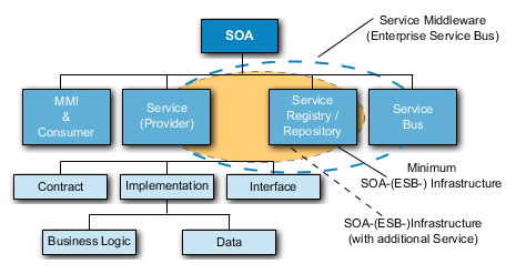
145. The application frontend (MMI) and Consumer for interaction between the user and a service and for the presentation of messages addressed to the user.
146. The main element of an SOA is the service as standardized implementation of certain functionality. A service is a self-describing open component that enables a fast and economical combination of dis-tributed applications.
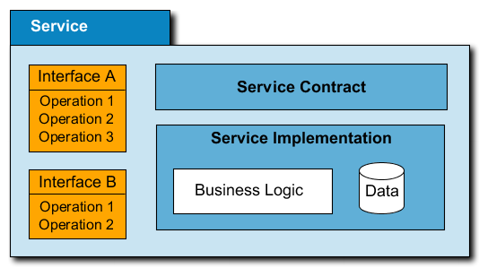
147. A service is made available by a provider und used by a consumer. The above figure shows the components of a service.
148. In order to make a service available as a SOA-service it has to fulfill certain conditions. It must be callable, show a defined functionality und stick to defined conditions. As a minimum, each service consists of three components: the interface, the “service contract” and the service implementation:
-
Service: The service itself must have a name or, if it shall be generally accessible, even a unique name.
-
Service Interface(s): Interfaces of the service that constitute the access point (one and the same service may have different interfaces).
-
Service Contract: The Service Contract is an informal specification of the responsibilities, the functionalities, the conditions and limitations and of the usage of the service.
-
Service Implementation: Is the technical realization of a service. Its main components are the reflection of the business-logic and the persistent storage of eventually necessary data.
149. A Service-Level-Agreement (SLA) or Quality-of-Service-Agreement (QSA) denotes a contract or interface, respectively between a consumer (customer) and a provider for recurring services.
150. The aim is to provide transparency on control options for the consumer and the provider by describing exactly assured performance characteristics like amount of effort, reaction time, and speed of processing. Its main part is the description of the quality of the service (service level) that has been agreed.
151. The Service-Registry / -Repository ensures that services are being found and executed and be deposited them through a service-bus.
152. If, for example a function is initiated on the application frontend that requires a service, the service-bus performs the necessary steps for connection. For that purpose the service-bus accesses the service-registry / repository and connects the right service (provider) with the right service client (consumer).
153. In summary, the function of a service-bus encompasses transmission, data transformation and routing of a message.
154. Beside its main task – to enable communication amongst the SOA-participants – the service-bus is also responsible for the technical service. This comprises logging, security, message transformation and the administration of transactions.
155. Differentiation to the Software Bus of the Enterprise Application Integration (EAI)
156. The concept of the service-bus guarantees a main advantage for the SOA-model against the classic EAI (Enterprise Application Integration). The EAI-approach uses a software bus, in order to connect two applications with the same technology whilst the service bus of a SOA offers a lot more flexibility because of its technological independence and the orientation of the services. The service bus supplements the EAI concept and so eliminates its weak points. These weak points are particularly its dependence on proprietary APIs, its uneven development behavior and manufacturer-dependant message formats.
157. Here the fundamental difference between a SOA and EAI becomes obvious. An EAI is focused on the coupling of autonomous applications in order to achieve useful possibilities for data processing of the overall application. In a SOA services are coupled only loosely and existing systems shall remain untouched whenever possible. Specifically, in a SOA the services are in focus, not the application systems.
158. Another advantage of SOA vs. EAI is the scalability of the service-bus. The EAI-concept is based on the "Hub-and-Spoke Method", where the software bus as a central point of contact connects the involved enterprise applications.
159. Definition of the SOA-(ESB-) Infrastructure and of the Enterprise Service Bus (ESB):
160. Unfortunately there is no universally applicable grouping of services, because the business processes of the companies / organizations are very different.
161. To achieve comparability, different definitions and groupings of services are considered and a corresponding mapping is made. For that purpose the following definition of a SOA- (ESB)-infrastructure is used:
-
SOA-(ESB-) Infrastructure:
A SOA-(ESB-) infrastructure provides core- and general services for operation and use of application services and applications.
The core of a SOA-(ESB-) infrastructure is formed by the service-registry / repository, through which application services and applications are provided with service descriptions and policies. Additionally the SOA- (ESB-) infrastructure comprises technical services for logging, security, message formatting and for administration of transactions.
-
Enterprise Service Bus (ESB):
The Enterprise Service Bus combines the service bus with its functions message transfer, date transformation and routing of the message with the SOA-(ESB-) infrastructure and amongst consumers (clients) und providers (service). So the ESB provides something like a service middleware to the consumers (clients) and providers (service) in order to use higher-value (application-) services.
C.2.3. Basic Model of a Service Reference Environment
162. A basic principle of SOA – Service Oriented Architecture – is a loose coupling of (web) services of operational systems, of different development languages and other technologies with underlaid applications. SOA separates functions in different services which can be accessed, combined and reused via a network.
163. The use of an Enterprise Service Bus (ESB), also named Enterprise Integration Bus, as a central component is meaningful for the connection of services for more complex, SOA-based solutions. Typically an ESB consists of a set of instruments for reliable and assured message-transfer, routing-mechanisms for message-distribution, pre-designed adaptors for the integration of different systems, management- and supervision-tools and other components.
164. The following figure depicts a general consumer-/ provider structure in a SOA environment. This figure is the basis for the considerations to follow and, despite its simplicity, it contains some important statements.
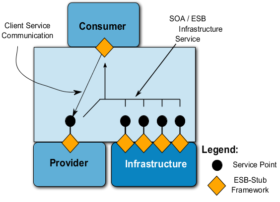
165. Generally a SOA configuration – and thus the reference environment SRE – consists of four main components:
-
Provider:A provider makes a service available to one or more consumers.
-
Consumer:A consumer is an application that uses a service of a provider. In turn, a consumer again may provide a service to other consumers.
-
Enterprise Service Bus (ESB): An ESB forms a kind of middleware that mediates between a service provider and one or more users (consumers). As a minimum the ESB routing, messaging, transformation, mapping and supervision etc.
-
SOA-(ESB-) Infrastructure: The SOA-(ESB-) Infrastructure-components is part of the ESB, by which basic services like e.g. directory- or security-services are provided.
166. In this generic, manufacturer-independent model the Enterprise Service Bus (ESB) iaw a virtual bus, that consists of only one component – ESB-Stub – , through which any further component (e.g. provider, consumer) is connected with the virtual bus. Depending on the type of component, either the provider, through the ESB-stub, provides a service-endpoint or a consumer uses a service of a provider trough the ESB-stub, respectively. The communication between consumer and provider is effected through the ESB-stub exclusively, though not via a central unit but directly. In the ESB-context, the infrastructure, like a provider, provides further services, which contain the ESB-stub as well.
167. Because further services are needed for the use of a service e.g. to obtain the service-description or for security and as these services are needed for every single use of a service, the ESB-stub executes these basic services automatically. For that reason the infrastructure in many cases is also being referred to as „SOA-(ESB-) Infrastructure“.
168. The following SRE capabilities can be derived from that:
-
A SRE configuration (operational system) consists of four main components: consumer, provider, SOA-(ESB-) Infrastructure and a virtual, distributed ESB.
-
A SRE configuration (operational) provides direct communication-relations between consumer and provider (without central components).
-
A reference environment for services (SRE) is based on different classifications of the providers (classes of services).
-
The service consumers and providers are using the SOA-(ESB-) Infrastructure for further services through an ESB (ESB-stub).
-
The SOA-(ESB-) Infrastructure-services form provider/service classes analogous to the classes of application-services.
-
The Enterprise Service Bus (ESB-Stub) takes over recurring routines of the application e.g. usage of the SOA-(ESB-) Infrastructure.
169. A substantial capability of a SOA Enterprise Service Bus is the standardized provision of services, i.e. the standardized access on providers and the provision of data, respectively. For that purpose the ESB, through its framework, provides to the consumers open, standardized service-endpoints of providers.
170. The following figure shows the structure of an open service-endpoint. Here the provider-application is connected to the (virtual, distributed) ESB through the ESB-stub (service container).
171. The ESB-stub contains a framework which is able to do e.g. routing, messaging, transformation, mapping, supervision-functions etc. The service-endpoint-interface encompasses the WSDL-description of the service. Through the ESB service endpoint the service is provided to the consumer’s iaw the WSDL-service-description.
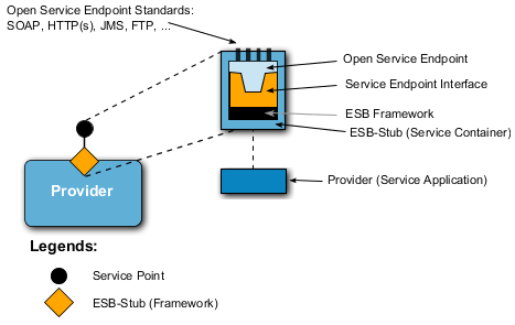
172. Standardized access to a service or the provision of data of a service, respectively, is realized through open Service Endpoint Standards like for example:
-
HTTP / HTTPS;
-
JMS;
-
SOAP / HTTP(s);
-
FTP (File Transfer Protocol);
-
Email (SMTP);
-
WS-Reliability / WS-Reliable Messaging;
-
Bridges or Gateways to other ESB Core Systems;
-
Manufacturer specific connectors (e.g. a SAP Connector).
173. In literature, these open service endpoint standards are referred to as Message Oriented Middleware (MOM) and form the core of an ESB-architecture (see the following figure).
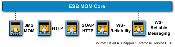
174. Using MOM, the transmitter and the receiver need a SW framework for the conversion of the message into or from MOM, respectively. The basic idea of MOM is a Multi Protocol Messaging Bus that supports transmission and forwarding of messages asynchronously while considering QoS (Quality of Service).
175. In context with anESB-Stub, that provides an open service-endpoint, the application-server has to be looked at.
176. In general an application-server is a server within a computer network, on which specialized services (application-services) are being executed. In the strict sense an application-server is software acting as a middleware representing a runtime environment for application-services. Depending on scaling they are assigned special services like transaction-administration, authentication or access on databases through defined interfaces.
177. The simplest variant of an application-server is an ESB-stub, that, iaw the SOA-mechanisms / -standards provides or integrates one special service whereas application-servers integrate multiple special services (application-services) through an ESB-Stub and, depending on their realization, offer more capabilities (functions).
178. Amongst others, through an ESB-stub / application-server the following functions are available:
-
start service,
-
stop service,
-
request status of a service,
-
unlock service for use,
-
lock/deny service for use.
179. However the ESB-Stub cannot support the function "star service", because no component is active that can accept and execute the demand for start on a provider that is shut down. This would require an additional agent. The functions being provided by an ESB-stub / application-server are used for example by a service management system.
180. This gives the following requirements for SRE:
-
Through the ESB (ESB-stub) the providers have to provide open, standardized service-endpoints to the consumers.
-
Through application-servers multiple providers have to be integrated and to be made available through a global, open service-endpoint.
-
The ESB-stub / application-server has to provide a service-management-interface, that enables; start service(s), stop service(s), deny service(s), unlock service(s), supervise service(s). Limitation: it may happen that a service cannot be started via the ESB-stub if the ESB-stub is inactive due to a stopped service.
C.2.4. Enterprise Service Bus OSI-Layer-Integration
181. This chapter briefly reviews the fundamentals and the ESB of a reference environment for services (SRE) will be assigned its place within the OSI reference model. Based on this, in the following chapter, the standards will be identified based on the WS-I profiles.
182. The following figure shows the ESB within the OSI-Layer-Model and its allocation to a specific layer, respectively.
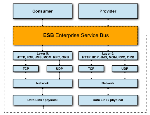
183. The Data Link / physical Layer encompasses the OSI-layers 1 (bit transfer) and 2 (security layer). On the bit-transfer-layer the digital transfer of bits is done on either on a wired or a non-wired transmission line. It is the task of the security layer (also being referred to as: section security layer, data security layer, connectivity security layer, connection layer or procedural layer) to ensure reliable transfer and to manage access onto the transmission media.
184. The Network Layer represents OSI-Layer 3 (Mediation Layer). For circuit-based services the mediation layer (also: packet-layer or network layer) does the switching of connections and for packet-oriented services it does the external distribution of data packages. The main task of the mediation layer is the built-up and update of routing tables and the fragmentation of data-packages.
185. Within the above figure dedicated as TCP and UDP – is the lowest layer that provides a complete end-to-end-communication between sender (transmitter) and recipient (receiver). It offers to the application-oriented layers 5 to 7 a standardized access, so they do not have to consider these features of the communication network.
186. The Session Layer corresponds to OSI-layer 5 (Communication Control Layer). It provides control of logical connections and of process communication between two systems. Here we find the protocols like HTTP, RPC, CORBA (IIOP, ORB), JMS, etc.
187. Above of the Communication Control Layer we find the Presentation Layer, which is OSI-Layer 6. The presentation layer translates the system-dependant presentation of data into a system-independent presentation and thereby enables the syntactically correct data-exchange between different systems. Also data-compression and data-encryption is a task of layer 6. The presentation layer ensures that data being sent from the application layer of one system can be read by the application layer of another system. If necessary the presentation layer acts as a translator between various data formats by using a data format that is under-stood by both systems.
188. The Enterprise Service Bus with its capabilities forms a possible realization of an OSI layer 6 (presentation layer), that is based on the functions of OSI layer 5 and enables access or provision of data for the applications (consumer, provider) at OSI layer 7.
189. In the following figure the ESB at OSI-layer 6 (presentation layer) is depicted in more detail and amended by essential standards that an ESB is based on.
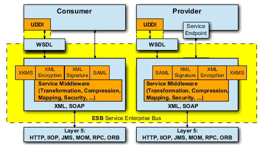
190. Through the service endpoint the provider provides a service that can be used by one or more con-sumers via the ESB. Additionally the ESB, through the SOA-(ESB-) infrastructure, currently offers an UDDI / ebXML-based directory service. Universal Description Discovery and Integration (UDDI) is a standardized directory for publication and search of services. UDDI is realized in numerous products; however there is no further development of UDDI. Electronic Business using XML (ebXML) is a family of different standards from UN/CEFACT and OASIS and comprises a registry service (Registry Service Specification) with a Registry Information Model (ebRIM). ebXML is relatively new, contains numerous urgently needed expansions of UDDI and is still under further development. However, ebXML is not yet available in many products.
191. UDDI and ebXML use Web Service Definition Language (WSDL) as service description language.
192. For example an ESB provides to a service-provider (Provider) and one or more users (Consumer) the following functions (extract):
-
Routing and Messaging as basic services;
-
Security (signature and encryption);
-
Transformation and Mapping, to execute various conversions and transformations;
-
Procedures for compression in order to reduce the amount of data for transmission;
-
A virtual communication bus, that permits the integration of different systems through pre-designed adaptors;
-
Mechanisms for the execution of processes and rules;
-
Supervision functions for various components;
-
A set of standardized interfaces like e.g. JMS (Java Messaging Specification), JCA (Java Connector Architecture) and SOAP / HTTP.
193. A standard to be highlighted amongst the others like e.g. JMS, that an ESB is based on, is SOAP (Simple Object Access Protocol) – a W3C-recommendation. SOAP is a “lightweight” protocol for the exchange of XML-based messages on a computer network. It establishes rules for message design. It regulates how data has to be represented in a message and how it has to be interpreted. Further on it provides a convention for remote call-up of procedures by using messages.
194. SOAP makes no rules on semantics of application-specific data that shall be sent but provides a framework which enables the transmission of any application-specific information.
195. SOAP is used for the remote call-up of procedures as well as for simple message systems or for data exchange. For the transmission of messages any protocols (OSI-Layer 5) such as FTP, SMTP, HTTP or JMS can be used.
C.2.5. Communication based on loose Coupling
196. A loose coupling – a basic SOA principle – is a principle and not a tool. When designing a SOA envi-ronment the amount of loose couplings to be established has to be determined.
197. Communication with an addressable communication partner can be effected in two ways:
-
In a connectivity-oriented communication environment the communication partner has to be dialed before information exchange actually starts and so a communication path between the two endpoints evolved is established through the net (a connection). Only then data can be exchanged (the data will always use the very same path through the net). When data exchange is terminated, the communication path is shut down. In general the address of the communication partner is only needed for the connection-built-up; then the net „remembers“, as well as the endpoints, which connection connects which endpoints.
-
Alternatively the job can be done connectionless: neitheran explicit communication-build-up before data exchange nor a shutdown thereafter must be executed. From the net perspective there is no established communication relation between two endpoints. Consequently there is no pre-determination of the path through the net during connection build-up. Instead each piece of information is addressed individually to the recipient and forwarded to the recipient by all other pieces of information based on this address in the net. All nodes in the net “know” on which paths to reach a certain destination. If there is more than one path from the sender to the recipient, different pieces of information may use different paths through the net.
198. From the communication technology-perspective the main difference is that in contrary to a connectivity-oriented communication no status information for each connection has to be stored in the connectionless communication environment. Two conclusions can be drawn from that:
-
The resistance to failure of the net increases. If in a connectivity-oriented communication a node in the net fails, all connections via this node are terminated; in connectionless communications the pieces of information are simply routed around the failing node and communication between the endpoints is hardly disturbed.
-
The net is more scalable because dimensioning of the nodes (e.g. computing power, memory capacity) will limit the number of possible connections via this node to a much smaller amount (because no status data on connections has to be kept within that node).
199. From the different methods of communication (connectivity-oriented vs. connectionless communica-tion) the following requirements for the application layer (service producer) can be drawn:
-
As radio-based communication systems cannot guarantee a connectivity-oriented communication, the radio-based communication between consumer and provider must be based on connectionless communication.
-
In wideband nets or if connectivity-oriented communication between consumer and provider is supported, communication between consumer and provider may also be realized in a connectivity-oriented manner.
200. This also gives a requirement for management services of a reference environment for services (SRE):
-
Through the service-registry (service-endpoint-definition) the service-management portion of SRE must identify the communication method to a service (provider) and provide it to the ESB-stub either before use of a service or through a (customer) policy deposited in the service registry. The communication method (connectivity-oriented or connectionless) gives a parameter for Quality of Service (QoS) for use of a service, that must be provided by the service-management portion of SRE differently (dynamically) depending on network configuration.
201. Middleware can be distinguished by the basic technology it uses: Data Oriented Middleware, Remote Procedure Call, Transaction Oriented Middleware, Message Oriented Middleware and Component Oriented Middleware.
202. The most common basic technology is the Message Oriented Middleware. It will be applied further on in the SRE. Here information exchange is realized with messages being transported by the middleware from one application to the next, starting from the ESB-stub. If necessary, message queues will be used.
203. Based on the communication methods Message Oriented Middleware may apply different message-exchange-patterns. The message-exchange-patterns differ in:
-
Request / Response: In this pattern the user sends a request to the service-provider and waits for a response. The components involved interact synchronously (and in most cases block each other!). The reaction follows immediately on the exchanged information. This pattern is mostly used by real-time-systems. In order to prevent an application blockade, the response can be awaited asynchronously. Therefore, in general synchronous (blocking) and asynchronous (non-blocking) Request / Response can be distinguished, where the asynchronous (non-blocking) Request / Response represents a kind of Request / Callback Pattern.
-
One-Way-Notification: If no response or confirmation is needed for a service call-up, then there is a simpler pattern as the request/response pattern. In One-Way-Notification a message is just sent („fire and forget“). An error message is then a for example a One-Way-Notification.
-
Request / Response via 2 One-Way-Notification: This is a special pattern composed of the two patterns described before. Here it has been taken into consideration that this causes an additional requirement for the SOA-(ESB-) infrastructure because the concrete sender of an One-Way-Notification must in turn also be the recipient of another (second) One-Way-Notification. Also it has to be noted that sequences of One-Way-Notifications are a process in itself.
-
Request / Callback: Often a consumer needs data or a feed-back without being blocked until it is received. This pattern is referred to as non-blocking or asynchronous Request / Response or Request / Callback, respectively. Here the consumer sends a request without blocking. I.e., a response is received when it is present or, if there is no response an autonomous response is sent, respectively. This higher flexibility however causes a higher amount of effort, because the application itself must ensure proper handling of asynchronous responses.
-
Publish / Subscribe: In this pattern a user registers with a consumer for specific notifications or events. This pattern allows several consumers to subscribe. For specific situations, events or state changes registered consumers are informed about this. The later distribution of events or state changes is realized using One-Way-Notifications towards registered consumers.
204. From this the following requirement for the Message Oriented Middleware (ESB-Stub) of the refer-ence environment for services (SRE) can be derived:
-
A Message Oriented Middleware – ESB-Stub – must support the different Message-Exchange-Patterns (synchronous), Request / Response, Request / Callback (asynchronous Request / Response), One-Way-Notification and Publish / Subscribe.
205. A message-exchange-pattern always depends on the characteristics of the related transport layer or the used protocol, respectively. Things may look different one layer above or below. Asynchronous message-exchange-patterns can be implemented on synchronous protocols and vice versa.
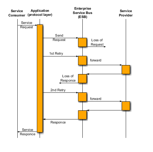
206. Even if the transport-layer is not reliable and messages might get lost, API may provide a virtually reliable message exchange. (This however may cause the disadvantage of undesired additional delay having great influence on the availability and QoS of that service). If, for instance, a consumer sends a request and is then blocked and the request gets lost so that the consumer would not be informed about it, then API could send a second request some time later (see above figure).
207. From the SOA perspective two things are important: Which Message-Exchange-Patterns support the underlaid protocol and which Message-Exchange-Patterns eventually support an API.
208. If the ESB is protocol-driven, most likely the application is responsible to embody a corresponding mechanisms of an API. If the ESB is API-driven, it is the responsibility of the ESB to support corresponding mechanisms.
209. Beyond the facts described above there are further complex requirements. For example they result from the situation, that an application performs a retry because it didn‘t get a response within time-out. In this case the application might just have assumed a lost response. After the retry the application then gets two responses. It could also happen that two requests (orders) had been sent. This could result in a double debit entry on a bank account instead of only one – as was desired.
C.2.6. Cross-domain Service Use and Interoperability
210. As an information domain is not an island but is required to provide information across domain borders – part of a Networked Operation (NetOpFü) – a cross-domain service use is necessary.
211. With a cross-domain service use, it is important to note that Bundeswehr assignments in SRE should be carried out in the Joint and Combined environment. This means that cross-domain service use does not only occur within its own (national) technical domain but also within technical domains of external partners (e.g. NATO partners).
212. For the purpose of implementing a cross-domain usage of services, no difference is made between internal and external usage. Instead, a united mechanism is adopted.
213. A cross-domain use of services calls for an interoperability of the provider and consumer both internally and externally. In order to maintain a common understanding, the definitions of interoperability are now briefly re-capped:
-
Operational interoperability denotes the existence of doctrines, operating procedures and common standards for human-machine interfaces.
-
Procedural interoperability is then guaranteed when common protocols for exchanging in-formation between platforms are applied and if there are common data definitions in the software.
-
Technical interoperability is ensured when common technical parameters / interfaces for transmitting information are applied.
214. In addition, the ‘technical interoperability’ which forms the basis of the ‘procedural interoperability’ is considered in the context of an ESB.
215. The mechanisms of a cross-domain service use consist of two mechanisms, in accordance with the domain concept. The cross-domain service use on technical domains is based upon open standardized service end-points.
216. If a provider makes an open standardized service end point available in a technical domain, the ser-vice end point can be used by a consumer of the same domain, as well as by a consumer of a differ-ent technical domain.
217. In the following figure, the basic principle of the use of open, standardized service end points is depicted.
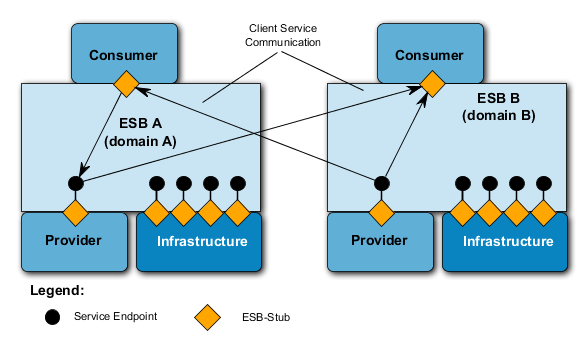
218. In general, a consumer needs information about the service (service description) in order to be able to use a service. The consumer typically receives such information from their own SOA (ESB) Infrastructure. In doing so, the SOA (ESB) Infrastructure of the technical domains to which the consumer is assigned, requires this information for a cross-domain service use.
219. So as to reduce interoperability problems and to guarantee self-sufficient consumer / provider configurations in a technical domain, the consumer and provider are assigned to a technical domain and for all infrastructure requirements, use the SOA (ESB) Infrastructure of the technical domains.
220. In order to get the information needed from the local technical domain to use a service beyond technical domain borders, this information must first be entered into the technical domain of the consumer.
221. To this end, a synchronization mechanism between the technical domains is provided through, which the relevant data for service use on technical domain borders is distributed (see the following figure).
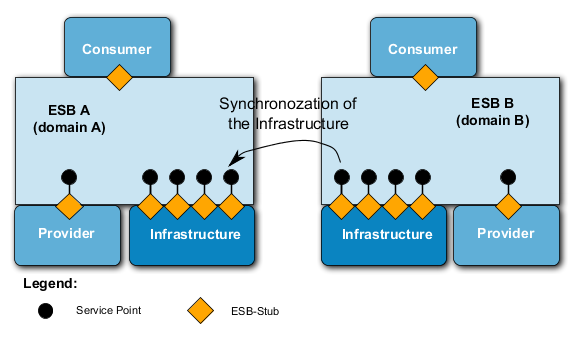
222. If every consumer in a cross-domain service use were to secure themselves the information (service description and policies) from the respective technical domains (SOA (ESB) Infrastructure), an exchange of this information would take place per consumer across domain borders. With targeted synchronization, the information exchange (service descriptions and policies) across domain borders would be restricted to a single exchange.
223. In summary, service use across technical domains occurs by means of an open, standardized service end-point and the synchronization of information (service description and policies).
224. Information domains are, as previously mentioned, user-specific domains which from an ESB perspective, are virtual and placed over technical domains. Generally speaking, a consumer or a provider can only be assigned to one technical domain. However, a provider can belong to several different information domains whereby consumers can use providers from different information domains.
225. The information domains are defined, among others, by authorization (policies) which are to be drawn up for services using the service description. The type of the authorization (policies) for a service can therefore vary greatly. For example, the authorization regulations may be composed of:
-
The classification of data of the service (security requirements);
-
The Quality of Service of the transmission medium (for example, broadband / narrowband of the transmission medium) which the service requires;
-
etc.
226. Synchronization between the information domains is not provided for, since the information necessary for a cross-domain service use is provided to the consumer via the SOA (ESB) Infrastructure in which this is statically recorded.
227. From the cross-domain use of services the following capabilities can be derived for the ESB:
-
The cross-domain use of services across technical domains is based on open, standardized end points.
-
Every consumer and provider is assigned to a technical domain which provides the consumer and provider with an SOA (ESB) Infrastructure. Exceptions to this rule are special consumers / providers (e.g. sensor fields) in the mobile environment as these do not possess their own SOA (ESB) Infrastructure.
-
The information (service description and policies) of a service, which is used across technical domain borders, is exchanged using special synchronization mechanisms between technical domains.
-
Every provider / service can be simultaneously assigned to several information zones (domains), yet at least one of these must be an information domain.
-
The information domains overall use of providers / services is regulated by means of authorizations (policies).
-
The authorizations (policies) are drawn up and supplied to the consumer via the SOA (ESB) Infrastructure of the technical domain assigned to him.
-
A consumer can, depending on his authorization, (policies) use provider /services of different information domains at the same time.
-
The provider checks the authorization regulations (policies) via the SOA (ESB) Infrastructure of the technical domains assigned to him.
C.2.7. Synchronization of SOA (ESB) Infrastructures
228. The number of technical domains on a national level will in the future be relatively high. Furthermore, own technical domains in the respective nations will exist with cross-nations service use and supply.
229. So that a consumer can get the information he requires from his local technical domain in order to gain access to a service beyond national or international domain borders, this must first be entered into the local technical domain of the service. For this reason, a synchronization mechanism between the technical domains is necessary via which the relevant data for the use of a service is distributed .
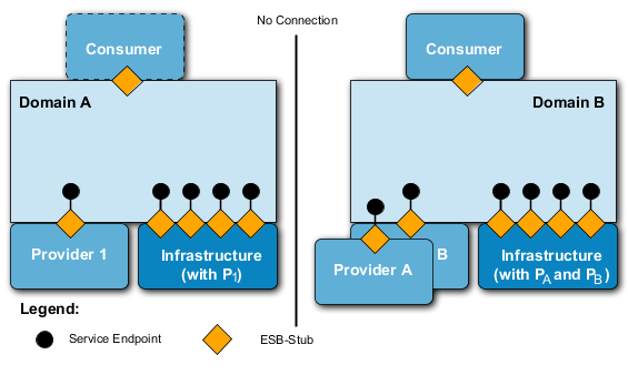
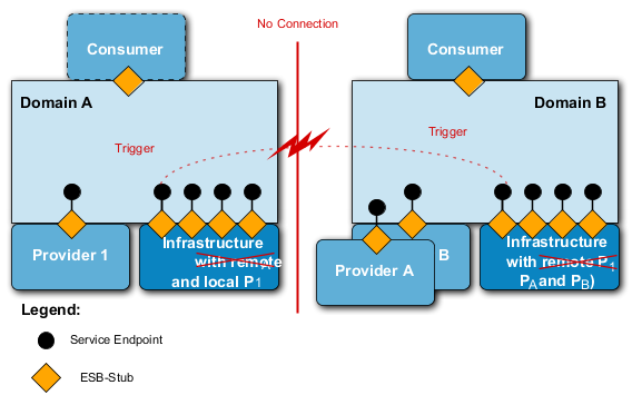
230. The following figure depicts the starting point of two technical domains which have no physical connection to one another. Both technical domains are self-sufficient and have consumer, provider and an SOA (ESB) Infrastructure which provides the consumers in the domains with information regarding the use of the locally assigned provider.
231. If both technical domains were to be physically connected and services on the technical domain borders to be used or provided, an infrastructure service of the respective domain must detect a new / additional technical domain and send a trigger to the SOA (ESB) Infrastructure service for synchronization.
232. Based on this initialization both synchronization services of the SOA (ESB) Infrastructure exchange service information which could be used on domain borders (see the following figure). Therefore, each domain only publishes local services which are provided via these domain borders. The synchronization service must thus take into account the underlying QoS parameters and policies. Using a corresponding service classification, the services for which a cross-domain use is permitted are determined and published.
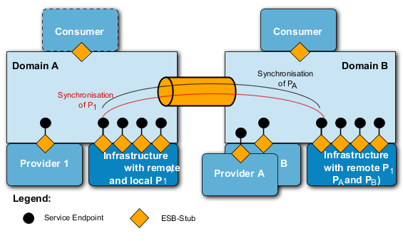
233. When two technical domains are synchronized, the respective synchronization service continuously checks whether the locally published service information has changed. If a change is detected, then a synchronizations update is conducted.
234. If both technical domains are physically separated (see the following figure), the network service detects that the other network is no longer available and subsequently informs the synchronization service which redelivers the published service information of this technical domain.
235. In the mobile environment (radio), mechanisms (e.g. Caching) should however be provided so as to compensate for any brief network fluctuations.
236. The synchronizations mechanism is independent from the equipment / provision of the technical domains. This means, for example, that the synchronization between mobile and portable / stationary domains can be identical to that in a federation of cross-nation domains. The services to be synchronized between different technical domains are determined according to a trust relationship and the QoS parameters (e.g. transmission medium, IT security).
237. Synchronization Data
238. Generally speaking, the service information of a service used cross-domain which must be synchronized is very extensive. The service information consists of the service description (WSDL file), policies, IT security data (e.g. public key) and the necessary QoS parameters. Overall, it is thought to be too expensive for synchronization in a narrowband network. For synchronizations across narrow band networks, prepared service forms are on hand and only a small section (e.g. provider name) is transmitted upon synchronization. For this reason, the synchronization data of the service descrip-tion for cross-domain used services must be differently scalable depending on bandwidth.
239. With broadband transmission mediums, more information can be exchanged, up to a complete service description (WSDL File, policies, IT security data and the necessary QoS parameters.
240. Conversely, with narrowband transmission mediums, only the characteristics of the service description are transmitted upon synchronization. Based on these characteristics, the services are registered in the SOA (ESB) infrastructure with the help of a pre-defined template (form) and thus published.
241. Due to this, the service descriptions of cross-domain used services are to be categorized in advance via templates and the IT security settings and QoS parameters correspondingly defined so that only the necessary characteristics are communicated during synchronization. The characteristics, IT security settings, QoS parameters, templates (forms) and the synchronization protocol used are to be standardized and – at least at NATO level – agreed upon.
242. From the synchronizations mechanism, the following capabilities for the ESB can be derived:
-
A synchronization service – assigned to SOA (ESB) Infrastructure – distributes service information to other technical domains when it receives a corresponding notification from a network service via a new node. If the synchronization service receives the message that a node/network is no longer available from the network service, it deletes the service information received from the technical domain assigned to the node / network from its own local SOA (ESB) Infrastructure. When using radio networks, this should not occur until after the adjustable ‘timeout’ period or until a Schmitt-Trigger-Function has occurred in order to ‘compensate’ for recurrent fluctuations in a radio network.
-
The synchronization service only publishes services across domain borders whose use beyond domain borders and for the underlying QoS parameter of the transmitting medium has been approved.
-
Services which are published by the synchronization service are categorized according to an approval for cross-domain use. Additionally, the QoS parameter (e.g. broadcast mediums, IT security) plays a part in the assessment of a cross-domain use.
-
A special operational case in the mobile area is ‘radio silence’. Here the status of the synchronization is controlled via manual processes. In a one-sided radio silence, synchronization data is transmitted to the receiving nodes by a multicast process and incorporated there.
-
The synchronizations data of the service description of cross-domain used services is scalable. On the one hand, even the complete service description (WSDL file), policies, IT security data and the necessary QoS Parameter can be exchanged in broadband networks. On the other, only the characteristics of the service description are exchanged in narrowband networks, on the basis of which the remote service is recorded and published in the SOA (ESB) Infrastructure.
243. From the synchronizations mechanism, the following requirements on the applications layer (service-producer) can be derived:
-
Based on pre-defined templates (forms) the services which are used cross-domain should be categorized. Therefore, corresponding IT security standards and QoS parameters are to be taken into account and specified. It is also to be indicated in the categorization whether the service is permitted to be used nationally or multi-nationally.
244. WS-Discovery
245. A special method for synchronisation between various domains is the OASIS WS-Discovery. Service Discovery is the process of finding the services that are available in the network. When operating in a wireless network environment where node mobility and shifting network conditions can cause network partitions and loss of network connections, it is vital to use a service discovery mechanism that does not rely on the availability of any given node. In other words, a fully distributed service discovery mechanism is needed. The only standardized Web service discovery protocol that currently fulfills this requirement by operating in a distributed mode is WS-Discovery.
246. WS-Discovery is designed for use in one of two modes: managed and ad hoc. In managed mode all nodes communicate through a discovery proxy, an entity which performs the service discovery function of behalf of all the other nodes, and which communicates with the other nodes using unicast messages. This mechanism can be used to achieve interoperability between registry based service discovery mechanisms and WS-Discovery.
247. In ad hoc mode, on the other hand, communication is fully distributed. Requests for service information are sent using multicast to a known address, and each node is responsible for answering requests from others about its own services. The ad hoc mode is intended to be used for local communication only, and the standard recommends limiting the scope of multicast messages by setting the time-to-live (TTL) field of the IPv4 header to 1, or by using a link-local multicast address for IPv6.
248. In several experiments the used tactical radio networks consist of a number of ad hoc networks connected to each other using Multi-Topology Routers (MTRs). The dynamic character of these networks implies that one cannot rely on a managed mode discovery proxy to remain available, meaning that the distributed ad hoc mode should be used. However, since this mode is limited to link local communication it will not provide the multi-network service discovery capability required in interconnected tactical networks. In order to work around this issue, it is recommended to allow the multicast discovery messages to travel across network boundaries by using e.g. a site-local IPv6 address, and increasing the Hop Limit in the IPv6 header. This solution works within a controlled network environment, but it is less than ideal for use in larger scale networks. That is because increasing the scope of the multicast messages might cause the messages to travel further than intended, and thus cause increased network load in networks where the messages are not needed.
249. As it is recommended to allow packets to flow across routers, a request sent by any one node in the network is received by all other nodes. If the message sent was a probe for available services, then all nodes that did offer a service matching the request would reply with a unicast message to the sender.
250. WS-Discovery can be completely integrated into an ESB, and connected to the internal service registry. This meant that any announcement made on WS-Discovery would be added to the service registry, which in turn meant that the announced service could be invoked from any consumer. If WS-Discovery is used as the only discovery mechanism it is used as a self-contained WS-Discovery application and therefore used for announcing and searching for services.
251. As mentioned above, allowing the multicast packets to traverse routers is not an ideal solution. An alternative is to combine the managed and ad hoc modes in one deployment. When a WS-Discovery proxy announces its presence, all other nodes are asked to enter managed mode, relying on the proxy for service discovery. However, the WS-Discovery specification does not require the nodes to change to managed mode, and by allowing the majority of nodes to remain in ad hoc mode and at the same time keep a link local message scope, one can secure local service discovery without the risk of generating unneeded network traffic in other networks. Combined with discovery proxies that function as relays between the networks, cross-network discovery can be achieved as well.
252. Note that, even though the WS-Discovery specification does allow nodes to choose not to enter managed mode when receiving a message telling it to do so, it does not clearly state what the expected behavior of nodes is once the network consists of nodes in both modes simultaneously. This combination of modes is desirable when working with multiple interconnected mobile networks, and therefore a profile of how to use the WS-Discovery standard in this context should be developed by NATO for interoperability between nations.
253. Because of the above mentioned priority of this service, it is recommended to add WS-Discovery to NATO's core services set.
C.2.8. Basic Security Considerations
254. One of the basic protocols of the ESB is the Simple Object Access Protocol (SOAP). SOAP is a standar-dized XML-based, platform-independent communication protocol for synchronous and asynchronous message exchanges between applications.
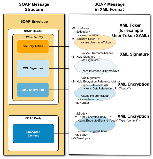
255. For the access or supply of classified information, the ESB offers a security concept (approach) in order to ensure protection of data / information objects (Property Protection). Property Protection is based upon XML/ SOAP messages and consists of the following basic technologies (see also the following figure):
-
XML Encryption: XML Encryption enables sections or individual elements of an XML document to be completely or partly encrypted. The encryption elements contain all encryption information.
-
XML Digital Signature: XML Digital Signature enables sections or individual elements of an XML document to be signed.
-
XML Token: XML Security Tokens describe how and which authentication mechanisms should be employed. Two Security Token mechanisms, X.509 Certificate and SAML Assertion are currently standardized.
256. Based on these basic technologies, for classified service information (data), exchange relationships, together with appropriate policies and security definitions for the exchange relationships are to be described.
257. The X.509 certificate mechanism will not be further discussed since it is a general security procedure and used via the PKI from ESB of the X.509 certificate mechanism.
258. The Security Assertion Mark-up Language (SAML) is an XML Framework for the exchange of authentication and authorization information. The SAML architecture provides functions to describe transmit and control safety-related information.
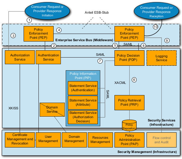
259. A Property Protection IT Security Architecture based on an SAML Architecture is depicted in the above figure. This forms an extended SAML Architecture since here a binding (authenticity), integrity, availability test is carried out on the part of the provider and consumer.
260. The individual steps which are processed via the Policy Enforcement Point or at the receiving end via the Policy Decision Point (PDP) are, depending on the predetermined service policies repeatedly running the same process steps.
261. Modeled on [8], the following possible steps are executed when accessing a service in the Property Protection of IT- Security Architecture (see above figure):
-
From the outset, the asset protection of the PEP (Policy Enforcement Point) is either triggered by a consumer request (data request) or a provider response (or notification).
-
Depending on the policy of the service (included in the service description), a certificate-based login is implemented (for example through the operating system) or the login data identified.
-
Before accessing a service, several certificates are required which may be created by the Public Key Infrastructure (PKI) and retrieved via XKISS
-
Upon accessing the service (properties previously determined using the ESB Service Registry), the PEP sends a SOAP request or upon response / notification, the PEP of the provider sends a SOAP response / notification via Middleware (ESB) to the provider or consumer. The PEP (Policy Enforcement Point) receives the SOAP request / response and then initiates an examination.
-
The PEP sends off the examination to the PDP (Policy Decision Point)
-
The PDP sends off a ‘policy query’ to the PRP (Policy Retrieval Point) which in turn answers with a ‘policy statement’.
-
Simultaneously, the PDP sends validation instructions (user, resource, and/or context attributes via ‘Statement Services’) to the PIP (Policy Information Point) which, using several additional services, checks the various information. Finally it sends the results to the PDP.
-
Based on the results, the PEP receives the outcome from the PDP.
-
At the same time, access to the service is logged by the PEP.
-
If all checks are successful and access granted, the PEP forwards the request to the provider or the response to the consumer.
262. Crucial to the Property Protection of IT Security Architecture is that both provider and consumer conduct a review of the binding (authenticity), integrity and availability of the respective partner. Only through such a mechanism can the binding (authenticity), integrity and availability of the respective partner in the mobile ESB field on the side of Property Protection be guaranteed.
263. Each service operation should be autonomous and require no other operation.
264. If only a single operation of a service is called up, and all security requirements met, the individual steps must be processed by the consumer and provider. However, these security technologies (encryption and signature) call for additional performance and bandwidth.
265. If several service operations are used in succession or it is assured that the use of a service takes place on a secured basic protection, the IT security steps for services in the mobile field with a low bandwidth should be optimized so that the complete examination does not have to be carried out upon every operation, in view of their performance and low bandwidth.
266. Such an approach calls for the capability on the part of an ESB (ESB Stub and SOA (ESB) Infrastruc-ture) to be able to manage and check policy settings, not just globally for one service but for different policies on the operational level of a service. Additionally, the service description (application level) states the requirement that global policies are not only to be developed for a service but also for every operation.
267. The security of information technology is an overarching challenge since every IT system considered individually frequently has its own security concept (and individual implementation) and consequently, its own security domain. An ESB-configuration with Property Protection is no exception.
268. A challenge, from the perspective of IT security, is to provide participants with classified data from a different security [2] or information [3] domain to their own (e.g. different authorizations of the users in the domains, different classifications of the domains.) To achieve this, cooperating security domains are required.
269. The binding (authenticity), integrity and availability test by the consumers and providers is carried out via the ESB Stub and the services of the assigned SOA (ESB) Infrastructure. In order to use the services of other security domains, the relevant security data / information from the respective security domain is required. Consequently, additional specialist services of the SOA (ESB) Infrastructure are necessary in order to, for example, synchronize the relevant security data/information of the co-operating security domains.
C.2.9. Notification
270. The specification: Web Services Notification (WS*-Notification) defines mechanisms for ap-plications which would like to generate, distribute or receive notifications (one-way notifica-tions). Here the Publish / Subscribe mechanism is used to which an application registers to receive (subscribe) certain notifications. Applications also provide notifications which should be distributed.
271. For different notification patterns, the following concepts are introduced
272. Publisher: A Publisher sends a notification to a Broker or to one or more Notification Con-sumers. A Publisher Application does not necessarily provide an open service endpoint.
273. Subscriber: A Subscriber conducts a subscription for a Notification Consumer application. In doing so, the Subscriber can also be the application for a Notification Consumer. A Subscriber Application provides an open service endpoint.
274. Notification Consumer:A Notification Consumer receives notifications. A ‘Push Consumer Application’ provides an open service endpoint on which the Notification Broker or the Notification Producer can send the notification asynchronously. A ‘Pull Consumer Application’ calls up an operation in the Notification Broker or Notification Producer in order to receive a notification.
275. In general, there are many different concepts and implementation possibilities for notification mechanisms. As an example, two different procedures are here presented.
276. Pattern: Notification Consumer / Subscriber and Publisher (Subscriber Manager)
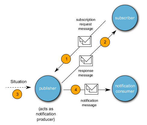
277. In this very simple notification pattern, an Application (subscriber) subscribes to an application (publisher) which sends the notification and receives a corresponding message (response) which the Notification Consumer receives when the event occurs. When it occurs (3), the Notification Publisher informs the Notification Consumer (4) – see next figure:
278. Whether the Notification Broker and the Notification Consumer form an application or whether they are divided into different applications is dependent on the selected architecture.
279. The Notification Pattern however allows both a separate and a combined implementation.
280. In a similar way, the Notification Publisher can also be implemented in two separate applications. Therefore, the Notification Publisher is divided into two parts, the Subscriber Manager and the Notification Publisher. The subscriber manager manages the subscriptions and gives these to the Notification Publisher. The Notification Publisher then distributes the notifications to the Notification Consumers based on the subscriptions.
281. Another notification pattern is the:
282. Pattern: Notification Broker, Publisher Registration Manager and Subscription Manager.
283. Here a network layer (network service) is inserted, on which the notification mechanism via Publish / Subscribe takes place:
-
The Notification Broker is a service which receives the received notifications from the Notification Producer (publisher) and distributes these to the registered Notification Consumer. In addition, via a Subscriber Manager (if a part of the Notification Producer), notifications are registered to a Notification Broker or modifications carried out.
-
The Publish Registration Manager provides an open service endpoint using which, ap-plications for notifications can be registered. These registered applications are delivered to the Notification Broker for it to send.
-
The Subscription Manager can be integrated into the application (Notification Broker) but can also be a separate application via which the notification could be created, access configured and adjustments made.
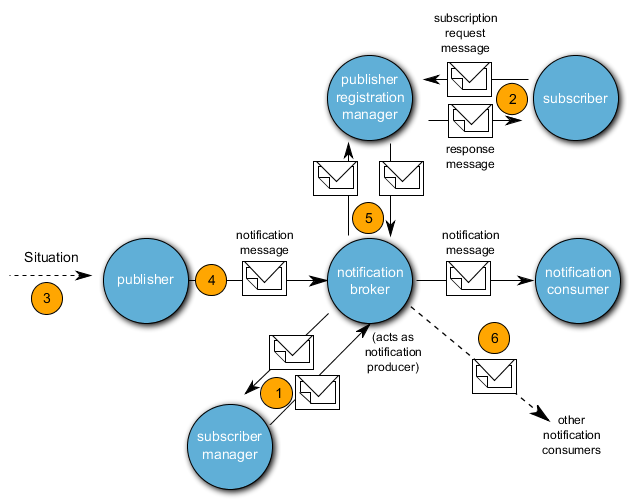
284. In the next Figure, the WS-*Notification Architecture for a Notification Broker is depicted. In the Notification Pattern via Notification Broker, the notifications which should be distributed are conveyed to the Notification Broker via a Subscriber Manager or are managed respectively (1). Notification Consumers register for the Publish Registration Manager via a Subscriber (2). If an event occurs with a Publisher (3), the Publisher sends the notification to the Notification Broker (4). The Notification Broker sends (6) the notification to the Notification Consumer communicated by the Publish Registration Manager.
285. The mechanism of the notification via Publish / Subscribe can be implemented in two possible ways. Therefore, there are also two specifications:
-
WS*-Notification Framework specifies data transfer for web services associated with the Publish-Subscribe process and is composed of the following standards:
-
WS*-Base Notification: defines service interfaces for Notification Producers and consumers which are required as basic roles for the notification message exchange.
-
WS*-Topic defines mechanisms relating to the organization and categorization of the interesting elements of subscriptions.
-
WS*-Brokered Notification defines the interface for Notification Brokers.
-
-
WS*-Eventing Specification WS*-Eventing enables the use of Publish/Subscribe design patterns in services. The Services Eventing Protocol defines messages for subscribing to an event source, for the termination of a subscription and for the sending of messages about events.
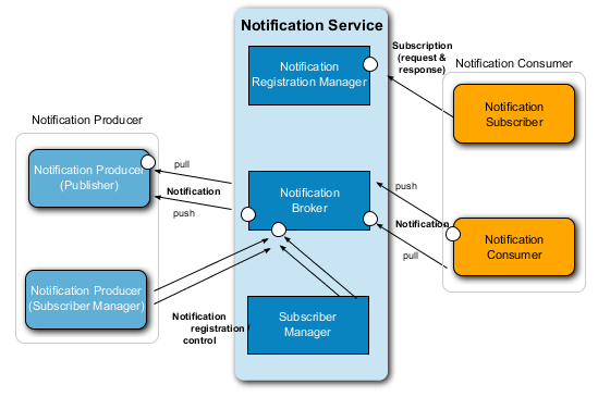
286. The architecture of the Notification Services according to the pattern: Notification Broker, Publisher Registration Manager and Subscription Manager is based on the WS*-Notification specification and thus contains the services:
-
Notification Registration Manager;
-
Notification Broker;
-
Notification Subscription Manager.
287. The service definition for the notification service is specified in [10].
[2] A security domain refers to a set of data, identities and services, for whose safety a particular organization (or person) is responsible.
[3] Information domains are those domains on an application level which are distinguished by certain properties e.g. user groups, organizational affiliation, authorizations and / or accessed information